Rockwell Automation 2097-Vxxx Kinetix 350 Single-axis EtherNet/IP Servo Drive User Manual User Manual
Page 138
138
Rockwell Automation Publication 2097-UM002C-EN-P - December 2013
Appendix A Interconnect Diagrams
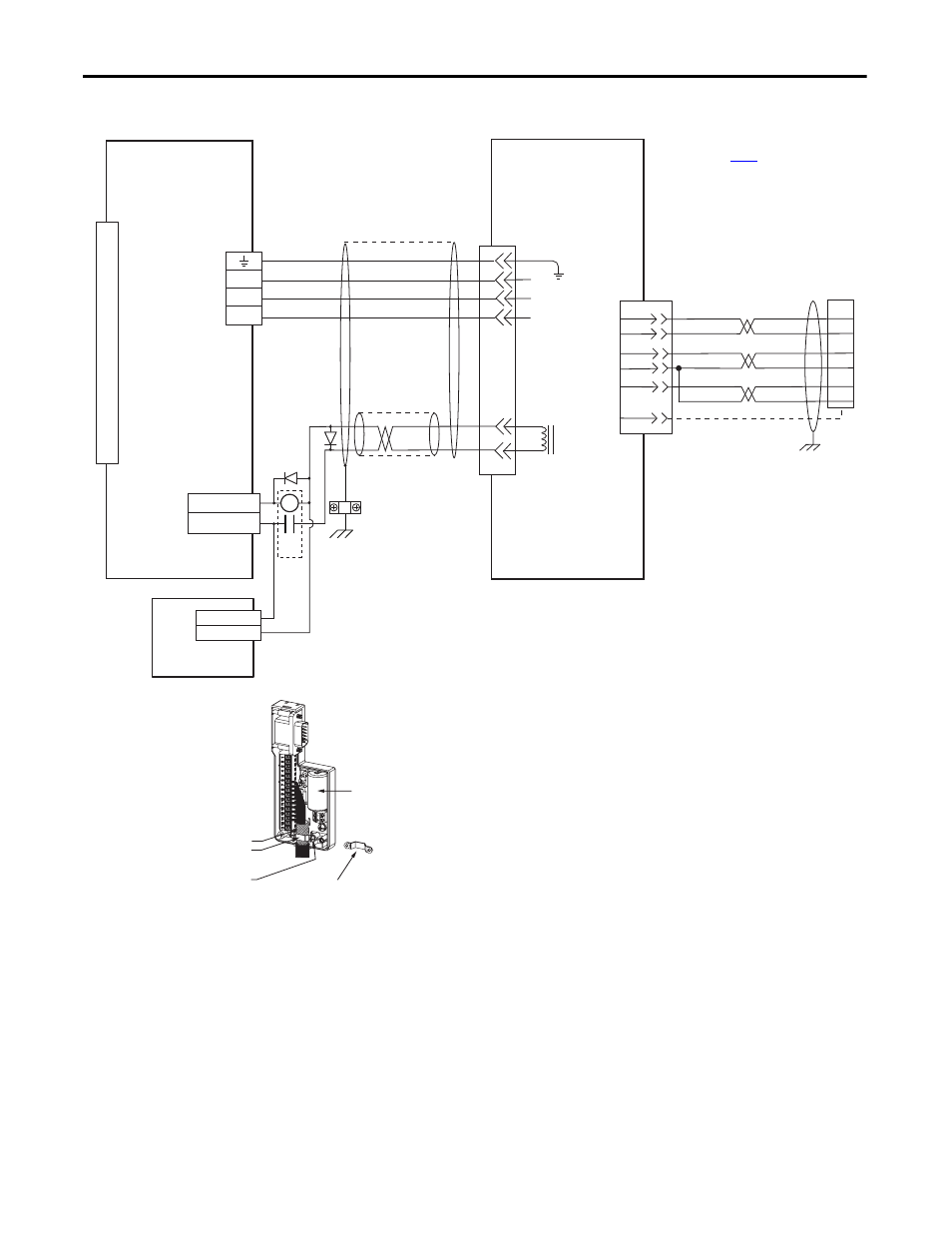
Figure 61 - Kinetix 350
Drive with TL-Series (Bulletin TLAR) Electric Cylinders
5
3
2
1
BR+
BR-
7
9
W
V
U
GND
0
1
2
3
4
5
6
7
8
9
10
11
12
13
14
15
GREEN/YELLOW
BLUE
BLACK
BROWN
BLACK
WHITE
W
V
U
+5VDC
ECOM
GRAY
WHT/GRAY
22
23
14
6
24
SHIELD
BAT+
BAT-
ORANGE
WHT/ORANGE
6
BAT+
BAT-
DATA+
DATA-
GREEN
WHT/GREEN
13
14
5
10
CR1
MTR_BRAKE -
MTR_BRAKE +
24V DC
24V DC COM
44
43
Motor Brake
Three-phase
Motor Power
Motor
Feedback
TLAR-Axxxxx-B (230V)
Servo Motors with
High Resolution Feedback
2090-K2CK-D15M
Connector Kit
2090-CFBM6DF-CBAAxx (flying-lead) or
2090-CFBM6DD-CCAAxx (with drive-end connector)
Feedback Cable
I/O (IOD)
Connector
Motor Power
(MP) Connector
2097-V3xPRx-LM
Kinetix 350 Drives
Motor Feedback
(MF) Connector
2090-CPBM6DF-16AAxx
Motor Power and Brake Cable
Notes 9, 10
Use 2090-CPWM6DF-16AAxx
cable for non-brake applications.
User Supplied
24V DC
Refer to low-profile connector
illustration (lower left)
for proper grounding technique.
Turn clamp over to hold
small cables secure.
Exposed shield secured
under clamp.
Clamp Screws (2)
Clamp
Refer to table on
3.6V battery (2090-DA-BAT2)
required for use with TLAR-Axxxxx-B electric cylinders
(high-resolution 17-bit encoders).
Cable Shield
Clamp
Low Profile Connector
(2090-K2CK-D15M shown)
Grounding Technique for
Feedback Cable Shield