Rockwell Automation 20B PowerFlex 700 AC Drives Vector Control (v4.001 and up) User Manual
Page 98
98
Rockwell Automation Publication 20B-UM002G-EN-P - July 2014
Appendix A
Supplemental Drive Information
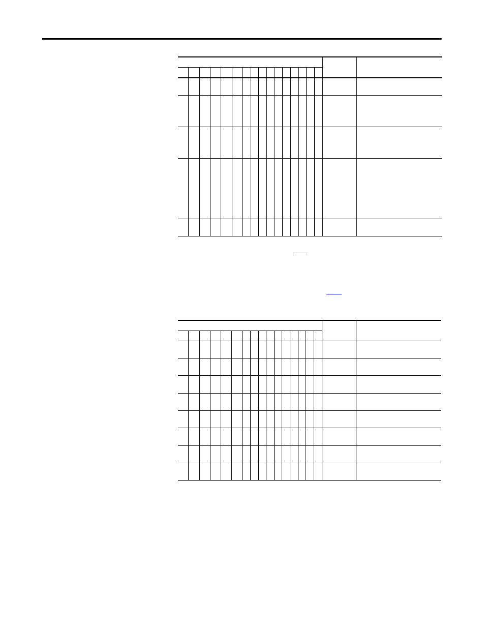
Table 14 - Logic Status Word
x
MOP
Increment
0 = Not Increment
1 = Increment
x
x
Accel Rate
00 = No Command
01 = Use Accel Time 1
10 = Use Accel Time 2
11 = Use Present Time
x
x
Decel Rate
00 = No Command
01 = Use Decel Time 1
10 = Use Decel Time 2
11 = Use Present Time
x
x
x
Reference
Select
(3)
000 = No Command
001 = Ref. 1 (Ref A Select)
010 = Ref. 2 (Ref B Select)
011 = Ref. 3 (Preset 3)
100 = Ref. 4 (Preset 4)
101 = Ref. 5 (Preset 5)
110 = Ref. 6 (Preset 6)
111 = Ref. 7 (Preset 7)
x
MOP
Decrement
0 = Not Decrement
1 = Decrement
(1)
A “0 = Not Stop” condition (logic 0) must first be present before a “1 = Start” condition will start the drive. The Start command acts as a momentary
Start command. A “1” will start the drive, but returning to “0” will not stop the drive.
(2) This Start will not function if a digital input (parameters 361-366) is programmed for 2-Wire Control (option 7, 8 or 9).
(3) This Reference Select will not function if a digital input (parameters 361-366) is programmed for “Speed Sel 1, 2 or 3” (option 15, 16
or 17). When using the Logic Command Word for the Speed Reference Selection, always set bit 12, 13, or 14 to “1.” Note that
Reference Selection is “Exclusive Ownership” see [Reference Owner] on
.
Logic Bits
Status
Description
15
14
13
12
11
10
9 8 7 6 5 4 3 2 1 0
x Ready
0 = Not Ready
1 = Ready
x
Active
0 = Not Active
1 = Active
x
Command
Direction
0 = Reverse
1 = Forward
x
Actual
Direction
0 = Reverse
1 = Forward
x
Accel
0 = Not Accelerating
1 = Accelerating
x
Decel
0 = Not Decelerating
1 = Decelerating
x
Alarm
0 = No Alarm
1 = Alarm
x
Fault
0 = No Fault
1 = Fault
Logic Bits
Command
Description
15
14
13
12
11
10
9 8 7 6 5 4 3 2 1 0