Rockwell Automation 20B PowerFlex 700 AC Drives Vector Control (v4.001 and up) User Manual
Page 144
144
Rockwell Automation Publication 20B-UM002G-EN-P - July 2014
Appendix C
Application Notes
Fast Brake
This method takes advantage of the characteristic of the induction motor whereby frequencies greater
than zero (DC braking) can be applied to a spinning motor that will provide more braking torque
without causing the drive to regenerate.
1. On Stop, the drive output will decrease based on the motor speed, keeping the motor out of the
regen region. This is accomplished by lowering the output frequency below the motor speed where
regeneration will not occur. This causes excess energy to be lost in the motor.
2. The method uses a PI based bus regulator to regulate the bus voltage to a reference (for example,
750V) by automatically decreasing output frequency at the proper rate.
3. When the frequency is decreased to a point where the motor no longer causes the bus voltage to
increase, the frequency is forced to zero. DC brake will be used to complete the stop if the DC
Braking Time is non-zero, then the output is shut off.
4. Use of the current regulator ensures that over current trips don’t occur and allow for an easily
adjustable and controllable level of braking torque.
5. Use of the bus voltage regulator results in a smooth, continuous control of the frequency and forces
the maximum allowable braking torque to be utilized at all times.
6. Important: For this feature to function properly the active Bus Reg Mode A or B must be set to
Adjust “Freq” and NOT be “Disabled.”
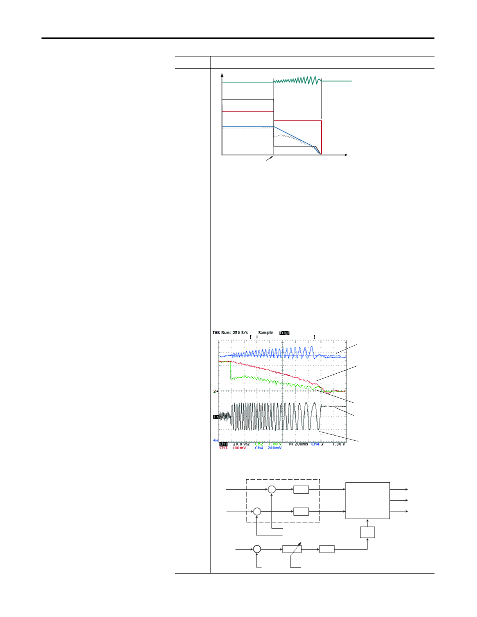
Test Example for Fast Braking
Implementation Block Diagram for Fast Braking
Mode
Description
Stop
Command
Time
Output Voltage
Output Current
Motor Speed
Bus Voltage
Command Speed
Bus Voltage
Motor Speed Feedback
Commanded Frequency
DC Brake Current
(Near Zero Speed)
Motor Current
Current Regulator
PI
PI
+
+
−
−
−
0
Brake
Level
IdCmd
IqCmd
T (
θ
)
θ
e
IqFdbk
IdFdbk
PI
Gain
Bus Voltage
Frequency
+
Bus Voltage
Reference
Vq
Vd
Va
Vb
Vc
fe
1/s