Rockwell Automation 20B PowerFlex 700 AC Drives Vector Control (v4.001 and up) User Manual
Page 28
28
Rockwell Automation Publication 20B-UM002G-EN-P - July 2014
Chapter 1
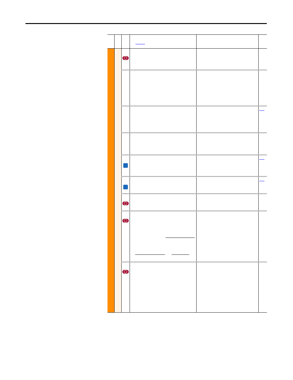
Programming and Parameters
MO
TO
R
C
O
N
TROL
Spee
d F
eedback
413 [Encoder PPR]
Contains the encoder pulses per revolution. For
improved operation in FVC Vector mode, PPR
should be ³ (64 x motor poles).
Default:
Min/Max:
Units:
1024 PPR
2/20000 PPR
1 PPR
414 [Enc Position Fdbk]
Displays raw encoder pulse count. For single
channel encoders, this count will increase (per
rev.) by the amount in [Encoder PPR]. For
quadrature encoders this count will increase by 4
times the amount defined in [Encoder PPR]. A
power cycle is required to reset this value.
Default:
Min/Max:
Units:
Read Only
–/+2147483647
1
415 [Encoder Speed]
Provides a monitoring point that reflects speed
as seen from the feedback device.
Default:
Min/Max:
Units:
Read Only
–/+420.0 Hz
–/+25200.0 RPM
0.1 Hz
0.1 RPM
416 [Fdbk Filter Sel]
Selects the type of feedback filter desired.
“Light” uses a 35/49 radian feedback filter.
“Heavy” uses a 20/40 radian feedback filter.
Default:
Options:
0
0
1
2
“None”
“None”
“Light”
“Heavy”
419 [Notch FilterFreq]
Sets the center frequency for an optional 2-pole
notch filter. Filter is applied to the torque
command. “0” disables this filter.
Default:
Min/Max:
Units:
0.0 Hz
0.0/500.0 Hz
0.1 Hz
420 [Notch Filter K]
Sets the gain for the 2-pole notch filter.
Default:
Min/Max:
Units:
0.3 Hz
0.1/0.9 Hz
0.1 Hz
421 [Marker Pulse]
Latches the raw encoder count at each marker
pulse.
Default:
Min/Max:
Units:
Read Only
–/+2147483647
1
422 [Pulse In Scale]
Sets the scale factor/gain for the Pulse Input
when P423 is set to “Pulse Input.” Calculate for
the desired speed command as follows:
Default:
Min/Max:
Units:
64
2/20000
1
423 [Encoder Z Chan]
Defines if the input wired to terminals 5 & 6 of
the Encoder Terminal Block will be used as a
Pulse or Marker input. Options 1 & 3 detect a loss
of signal (when using differential inputs)
regardless of the [Feedback Select], param. 080
setting. When option 2 or 3 is used with Profile/
Indexer mode, the “homing” routine will position
to the nearest marker pulse off of the home limit
switch.
Default:
Options:
0
0
1
2
3
“Pulse Input”
“Pulse Input”
“Pulse Check”
“Marker Input”
“Marker Check”
Fil
e
Gr
oup
No
.
Parameter Name & Description
See
page 16
for symbol descriptions
Values
Rela
ted
FV
FV
Input Pulse Rate (Hz)
Desired Cmd. (Hz)
Input Pulse Rate (Hz)
Desired Cmd. (RPM)
x
120
[Motor Poles]
for Hz, [Pulse In Scale] =
for RPM, [Pulse In Scale] =