Rockwell Automation 20B PowerFlex 700 AC Drives Vector Control (v4.001 and up) User Manual
Page 53
Rockwell Automation Publication 20B-UM002G-EN-P - July 2014
53
Programming and Parameters
Chapter 1
UTILIT
Y
Fa
u
lt
s
244
246
248
250
252
254
256
258
[Fault 1 Time]
[Fault 2 Time]
[Fault 3 Time]
[Fault 4 Time]
[Fault 5 Time]
[Fault 6 Time]
[Fault 7 Time]
[Fault 8 Time]
Default:
Min/Max:
Units:
Read Only
0.0000/214748.3647 Hr
0.0001 Hr
The time between initial drive power up and the occurrence of the associated trip fault. Can be
compared to [Power Up Marker] for the time from the most recent power up.
[Fault x Time] – [Power Up Marker] = Time difference to the most recent power up. A negative
value indicates fault occurred before most recent power up. A positive value indicates fault
occurred after most recent power up.
To convert this value to the number days, hours, minutes and seconds, the following formula can
be used:
Fault x Time/24 hours = (# of days).(remaining time)
Remaining Time x 24 hours = (# of hours)
Remaining Time x 60 minutes = (# of minutes).(remaining time)
Remaining Time x 60 seconds = (# of seconds)
Result = (# of days).(# of hours).(# of minutes).(# of seconds)
Example:
1909.2390 Hrs / 1 Day/24 Hrs = 79.551625 Days
0.551625 Days x 24 Hrs/Day = 13.239 Hrs
0.239 Hrs x 60 Min/Hr = 14.34 Min
0.34 Min x 60 Sec/Min = 20.4 Secs
Alarms
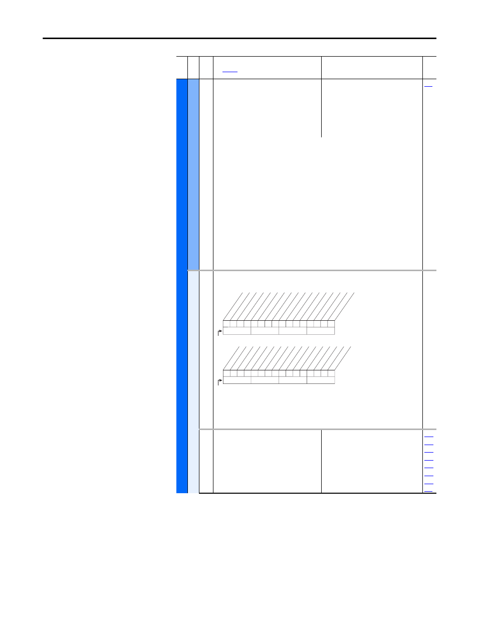
259 [Alarm Config 1]
Enables/disables alarm conditions that will initiate an active drive alarm.
Description
OW Trq Level, bit 19For the Rod Torque Process Display to work, the Oil Well Torque Level must be
enabled.
261 [Alarm Clear]
Resets all [Alarm 1-8 Code] parameters to zero.
Default:
Options:
0
0
1
“Ready”
“Ready”
“Clr Alrm Que”
262
263
264
265
266
267
268
269
Fil
e
Gr
oup
No
.
Parameter Name & Description
See
page 16
for symbol descriptions
Values
Rela
ted
1
1
1
1
1
1
x
1
1
1
1
0
0
0
0
x
10
0
1
2
3
4
5
6
7
8
9
11
12
13
14
15
1 = Condition True
0 = Condition False
x = Reserved
Bit #
Pr
echr
g A
ct
v
UnderV
oltage
Po
w
er L
oss
Str A
t P
wrUp
Anlg in L
oss
In
tDBRes OH
Dr
v OL L
vl 1
Dr
v OL L
vl 2
Dec
el Inhibt
W
aking
Mot
or T
herm
In PhaseL
oss
Load L
oss
Gr
ound W
arn
1
0
0
0
1
1
1
1
x
x
x
x
x
x
x
x
26
16
17
18
19
20
21
22
23
24
25
27
28
29
30
31
1 = Condition True
0 = Condition False
x = Reserved
Bit #
Adj V
olt
Ref
Pr
of S
etHome
PT
C HW
DPI P1 L
oss
(2)
DPI P2 L
oss
(2)
DPI P3 L
oss
(2)
OW T
rq
Lev
el
Ac
tiv
e Cn
vtr
(1)
(1)
Firmware 6.002 and later.
(2)
Firmware 9.001 and later.