Rockwell Automation 20B PowerFlex 700 AC Drives Vector Control (v4.001 and up) User Manual
Page 34
34
Rockwell Automation Publication 20B-UM002G-EN-P - July 2014
Chapter 1
Programming and Parameters
SPEED C
O
MMAND
Sli
p C
om
p
Important: Parameters in the Slip Comp Group are used to enable and tune the Slip
Compensation Regulator. In order to allow the regulator to control drive operation, parameter
080 [Speed Mode] must be set to 1 “Slip Comp”.
121 [Slip RPM @ FLA]
Sets the amount of compensation to drive output
at motor FLA. Slip RPM @ FLA = Synchronous
Speed - Motor Nameplate RPM
If the value of parameter 061 [Autotune] = 3
“Calculate” changes made to this parameter will
not be accepted.
Value can be changed by [Autotune] when
“Encoder” is selected in [Feedback Select],
parameter 080.
Default:
Min/Max:
Units:
Based on [Motor NP RPM]
0.0/1200.0 RPM
0.1 RPM
122 [Slip Comp Gain]
Sets the response time of slip compensation.
Default:
Min/Max:
Units:
40.0
1.0/100.0
0.1
123 [Slip RPM Meter]
Displays the present amount of adjustment
being applied as slip compensation.
Default:
Min/Max:
Units:
Read Only
–/+300.0 RPM
0.1 RPM
Proc
ess
P
I
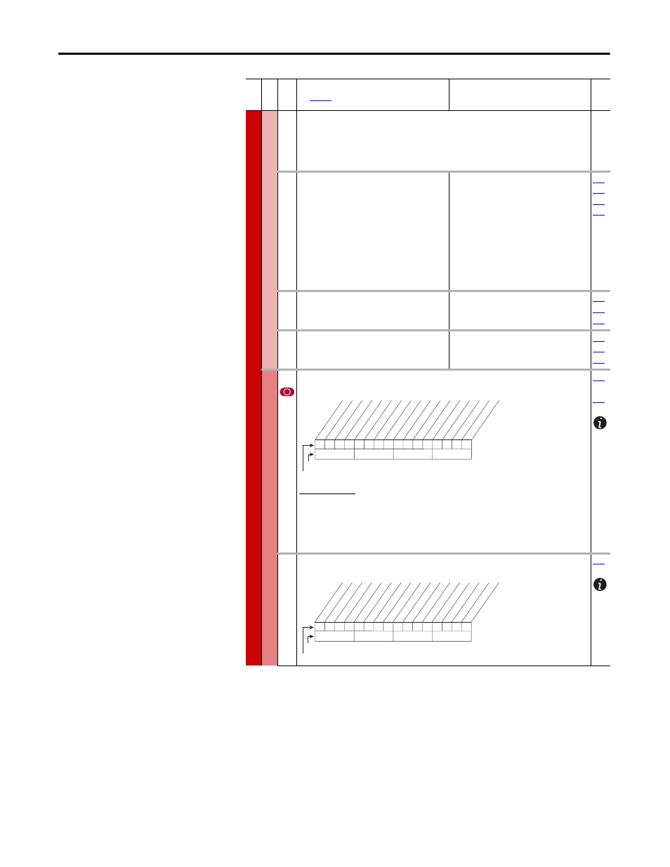
124 [PI Configuration]
Sets configuration of the PI regulator.
Option Description
AdjVoltTrim (10) Configures the PI regulator output to trim the voltage reference, rather than
the torque or speed references. The trim can be configured to be exclusive by
setting “Excl Mode” (bit 0). Trimming the voltage reference is not compatible
with trimming the torque reference, thus if bits 8 & 10 are set, a type II alarm
will occur, setting “PI Cfg Cflct” (bit 19) in [Drive Alarm 2].
…
125 [PI Control]
Controls the PI regulator.
Fil
e
Gr
oup
No
.
Parameter Name & Description
See
page 16
for symbol descriptions
Values
Rela
ted
0
0
0
0
0
0
0
0
0
0
0
x
x
x
x
x
10
0
1
2
3
4
5
6
7
8
9
11
12
13
14
15
1 = Enabled
0 = Disabled
x = Reserved
Bit #
Factory Default Bit Values
Ex
cl Mode
In
ve
rt Err
or
Pr
eload Mode
Ramp Ref
Zer
o Clamp
Feedbak S
qr
t
St
op Mode
An
ti-
W
ind Up
Tor
que T
rim
% of Ref
AdjV
oltT
rim
0
0
x
0
x
x
x
x
x
x
x
x
x
x
x
x
10
0
1
2
3
4
5
6
7
8
9
11
12
13
14
15
1 = Enabled
0 = Disabled
x = Reserved
Bit #
Factory Default Bit Values
PI Enable
PI Hold
PI Reset