Precharge board led indications, Him indication, Manually clearing faults – Rockwell Automation 20B PowerFlex 700 AC Drives Vector Control (v4.001 and up) User Manual
Page 85: Precharge board led indications him indication
Rockwell Automation Publication 20B-UM002G-EN-P - July 2014
85
Troubleshooting
Chapter 2
Precharge Board LED Indications
Precharge Board LED indicators are found on AC input drives, Frames 5…10.
HIM Indication
The LCD HIM also provides visual notification of a fault or alarm condition.
Manually Clearing Faults
Name
Color
State
Description
Power
Green
Steady
Indicates when precharge board power supply is operational
Alarm
Yellow
Flashing
[1]
[2]
[3]
[4]
[5]
[6]
[7]
Number in “[ ]” indicates flashes and associated alarm
(1)
:
Low line voltage (<90%).
Very low line voltage (<50%).
Low phase (one phase <80% of line voltage).
Frequency out of range or asymmetry (line sync failed).
Low DC bus voltage (triggers ride-through operation).
Input frequency momentarily out of range (40-65 Hz).
DC bus short circuit detection active.
(1) An alarm condition automatically resets when the condition no longer exists.
Fault
Red
Flashing
[2]
[4]
Number in “[ ]” indicates flashes and associated fault
(2)
:
DC bus short (Udc <2% after 20 ms).
Line sync failed or low line (Uac <50% Unom).
(2) A fault indicates a malfunction that must be corrected and can only be reset after cycling power.
Condition
Display
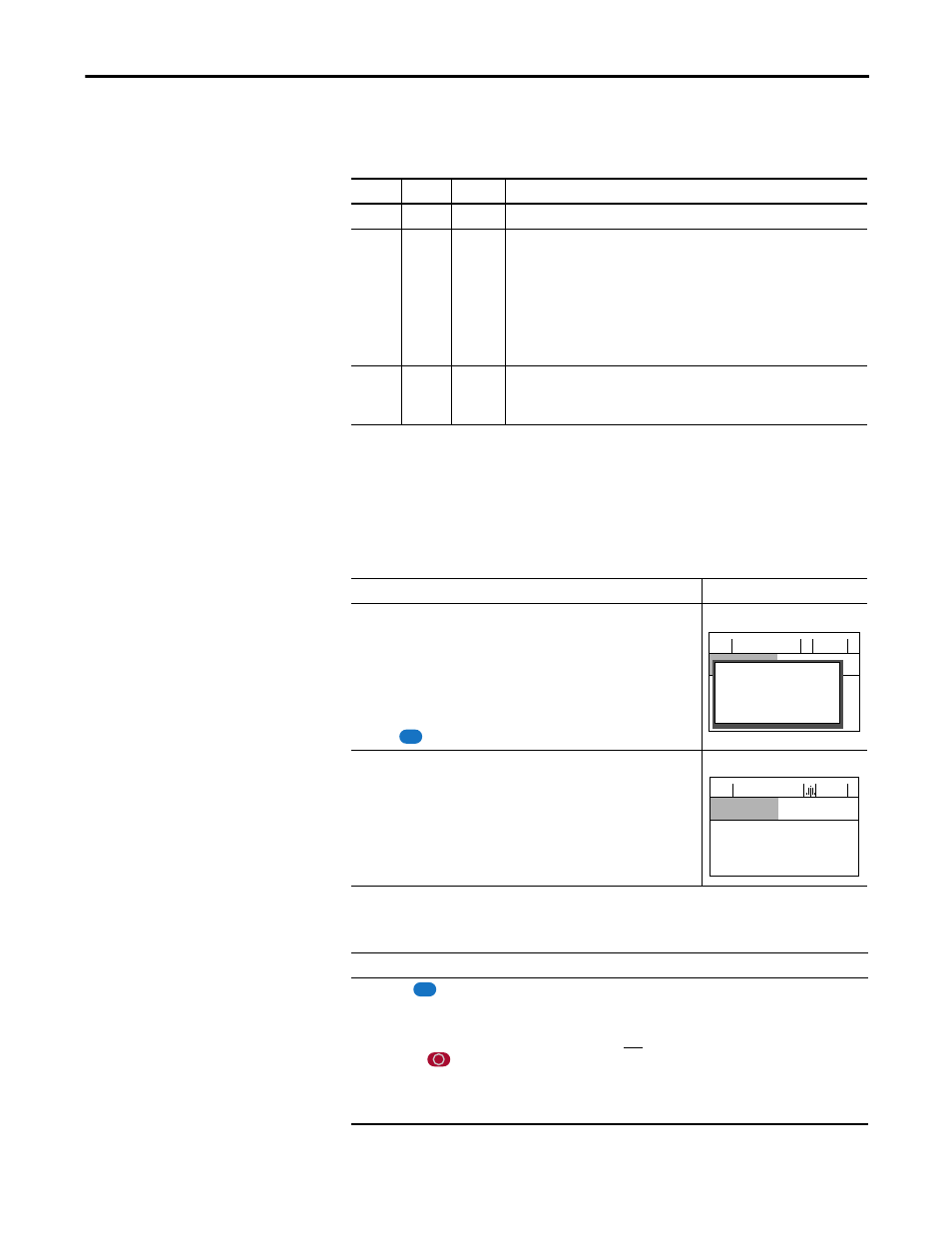
Drive is indicating a fault
The LCD HIM immediately reports the fault condition by displaying the
following.
• “Faulted” appears in the status line
• Fault number
• Fault name
• Time that has passed since fault occurred
Press the
key to regain HIM control.
Drive is indicating an alarm
The LCD HIM immediately reports the alarm condition by displaying the
following.
• Alarm name (Type 2 alarms only)
• Alarm bell graphic
Esc
F-> Faulted
Auto
0.0
Hz
Main Menu:
Diagnostics
Parameter
— Fault — F
5
OverVoltage
Time Since Fault
0000:23:52
F-> Power Loss
Auto
0.0
Hz
Main Menu:
Diagnostics
Parameter
Device Select
Step
1. Press the
key to acknowledge the fault. The fault information will be removed so that you can use the HIM.
2. Address the condition that caused the fault.
The cause must be corrected before the fault can be cleared.
3. After corrective action has been taken, clear the fault using one of these methods.
– Press the
(Stop) key.
– Cycle drive power.
– Set parameter 240 [Fault Clear] to “1.”
– “Clear Faults” on the HIM Diagnostic menu.
Esc