Inputs & outputs file, Logic mask – Rockwell Automation 20B PowerFlex 700 AC Drives Vector Control (v4.001 and up) User Manual
Page 59
Rockwell Automation Publication 20B-UM002G-EN-P - July 2014
59
Programming and Parameters
Chapter 1
Inputs & Outputs File
CO
MM
UN
IC
ATI
O
N
S
Secu
ri
ty
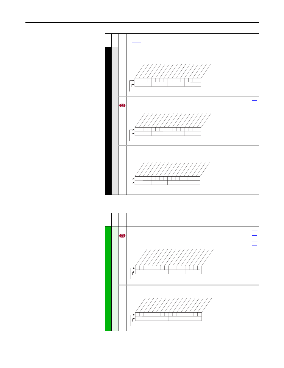
597 [Write Mask Act]
Read Only
Status of write access for DPI ports. When bit 15 is set, network security is controlling the write
mask instead of [Write Mask Cfg].
276 [Logic Mask]
Determines which ports can control the drive. If the bit for a port is set to “0,” the port will have
no control functions except for stop.
…
598 [Logic Mask Act]
Read Only
Indicates status of the logic mask for DPI ports. When bit 15 is set, network security is controlling
the logic mask instead of [Logic Mask].
Fil
e
Gr
oup
No
.
Parameter Name & Description
See
page 16
for symbol descriptions
Values
Rela
ted
1
1
1
x
1
1
1
x
x
x
x
x
x
x
x
0
10
0
1
2
3
4
5
6
7
8
9
11
12
13
14
15
1 = Write Permitted
0 = Read Only
x = Reserved
Bit #
Factory Default Bit Values
DPI P
or
t 1
DPI P
or
t 2
DPI P
or
t 3
DPI P
or
t 4
DPI P
or
t 5
DPI P
or
t 6
(1)
Se
curit
y
(1)
Firmware 6.002 and later.
1
1
1
1
1
1
1
x
x
x
x
x
x
x
x
x
10
0
1
2
3
4
5
6
7
8
9
11
12
13
14
15
1 = Control Permitted
0 = Control Masked
x = Reserved
Bit #
Factory Default Bit Values
Digital In
DPI P
or
t 1
DPI P
or
t 2
DPI P
or
t 3
DPI P
or
t 4
DPI P
or
t 5
DPI P
or
t 6
(1)
(1)
Firmware 6.002 and later.
1
1
1
1
1
1
1
x
x
x
x
x
x
x
x
0
10
0
1
2
3
4
5
6
7
8
9
11
12
13
14
15
1 = Control Permitted
0 = Control Masked
x = Reserved
Bit #
Factory Default Bit Values
Digital In
DPI P
or
t 1
DPI P
or
t 2
DPI P
or
t 3
DPI P
or
t 4
DPI P
or
t 5
DPI P
or
t 6
(1)
Se
curit
y
(1)
Firmware 6.002 and later.
Fil
e
Gr
oup
No
.
Parameter Name & Description
See
for symbol descriptions
Values
Rela
ted
INPUT
S & OUTPUTS
An
al
og In
pu
ts
320 [Anlg In Config]
Selects the mode for the analog inputs.
For current mode, verify that wiring is correct at I/O terminals 17/18 (Analog In 1) or 19/20
(Analog In 2). Refer to the Installation Instructions for details.
321 [Anlg In Sqr Root]
Enables/disables the square root function for each input.
0
x
x
0
x
x
x
x
x
x
x
x
x
x
x
x
10
0
1
2
3
4
5
6
7
8
9
11
12
13
14
15
1 = Current
0 = Voltage
x = Reserved
Bit #
Factory Default Bit Values
An1 0=V 1=mA
An2 0=V 1=mA
0
x
x
0
x
x
x
x
x
x
x
x
x
x
x
x
10
0
1
2
3
4
5
6
7
8
9
11
12
13
14
15
1 = Enable
0 = Disable
x = Reserved
Bit #
Factory Default Bit Values
Analog In 1
Analog In 2