Rockwell Automation 20B PowerFlex 700 AC Drives Vector Control (v4.001 and up) User Manual
Page 92
92
Rockwell Automation Publication 20B-UM002G-EN-P - July 2014
Chapter 2
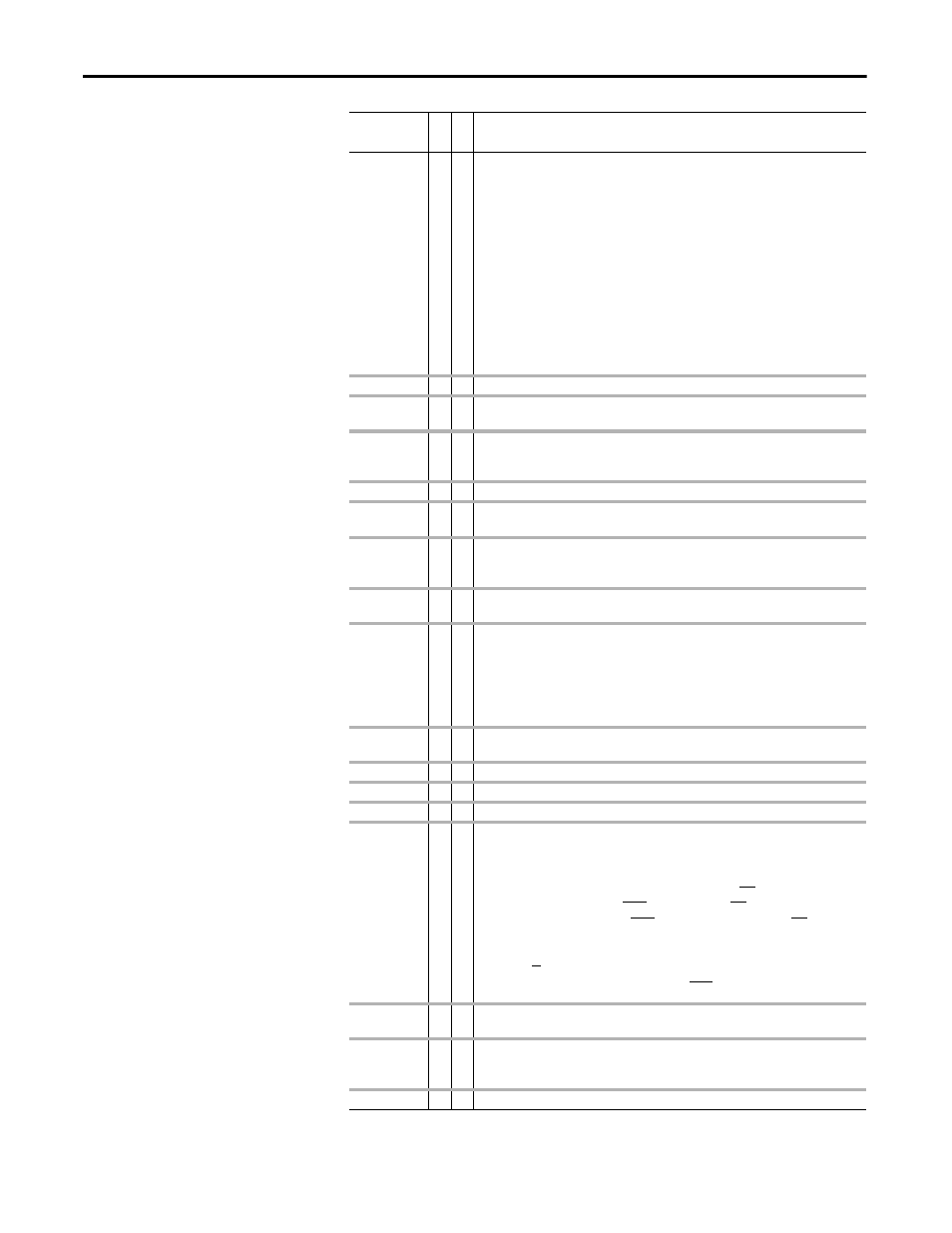
Troubleshooting
Home Not Set
34
1 Configurable alarm set in parameter 259, bit 17. When set to “1,” this alarm is displayed
when any of the following occur:
• parameter 88 is set to “7” (Pos/Spd Prof)
• on power up and parameter 88 = “7”
• recall user sets and parameter 88 = “7”
Alarm is cleared when:
• setting parameter 88 to a value other than “7”
• reset defaults
• parameter 259, bit 17 is cleared
• a digital input is configured as “Set Home” and input is True
• parameter 705, bit 9 is “Enabled”
• parameter 700, bit 13 (At Home) is “Enabled” - position regulator will set this bit if
device is “home”
In Phase Loss
13
1 The DC bus ripple has exceeded a preset level.
IntDBRes
OvrHeat
6
1 The drive has temporarily disabled the DB regulator because the resistor temperature has
exceeded a predetermined value.
IR Volts Range
25
2 The drive auto tuning default is “Calculate” and the value calculated for IR Drop Volts is not
in the range of acceptable values. This alarm should clear when all motor nameplate data is
properly entered.
Ixo Vlt Rang
28
2 Motor leakage inductance is out of range.
Load Loss
14
1 Output torque current is below [Load Loss Level] for a time period greater than [Load Loss
time].
MaxFreq Conflict 23
2 The sum of [Maximum Speed] and [Overspeed Limit] exceeds [Maximum Freq]. Raise
[Maximum Freq] or lower [Maximum Speed] and/or [Overspeed Limit] so that the sum is
less than or equal to [Maximum Freq].
Motor
Thermistor
12
1 The value at the thermistor terminals has been exceeded.
Motor Type Cflct 21
2 [Motor Type] has been set to “Synchr Reluc” or “Synchr PM” and one or more of the
following exist:
• [Motor Cntl Sel] = “Sensrls Vect,” “SV Economize” or “Fan/Pmp V/Hz.”
• [Flux Up Time] is greater than 0.0 Secs.
• [Speed Mode] is set to “Slip Comp.”
• [Autotune] = “Static Tune” or “Rotate Tune.”
NP Hz Conflict
22
2 Fan/pump mode is selected in [Motor Cntl Sel] and the ratio of [Motor NP Hertz] to
[Maximum Freq] is greater than 26.
PI Config Conflict 52
2 Check [PI Configuration], both “AdjVoltTrim” & “Torque Trim” are selected.
Power Loss
3
1 Drive has sensed a power line loss.
Precharge Active 1
1 Drive is in the initial DC bus precharge state.
Prof Step Cflct
50
2 An error is detected in trend step(s).
• Set if Sleep Mode is enabled.
• Set if:
any profile step uses “Encoder Incr” and/or “Enc Absolute” and
[Motor Cntl Sel], parameter 53 is not set to “FVC Vector” and
[Feedback Select], parameter 80 is not set to “Encoder” or “Simulator” and [Speed/
Torque Mod], parameter 88 = “7” (Pos/Spd Prof).
• a Step Type is configured for “Dig Input” and the Step Value is greater than 6, less than -
6, or zero or
the digital input selected with [Digital Inx Sel] is not set to “57, Prof Input.”
• Cleared if none of the above occur.
PTC Conflict
31
2 PTC is enabled for Analog In 1, which is configured as a 0-20 mA current source in [Anlg In
Config].
Sleep Config
29
2 Sleep/Wake configuration error. With [Sleep-Wake Mode] = “Direct,” possible causes
include: drive is stopped and [Wake Level] < [Sleep Level].“Stop=CF,” “Run,” “Run
Forward,” or “Run Reverse” is not configured in [Digital Inx Sel].
Speed Ref Cflct
27
2 [Speed Ref x Sel] or [PI Reference Sel] is set to “Reserved”.
Alarm
No
.
Ty
pe
(1)
Description