Rockwell Automation 20B PowerFlex 700 AC Drives Vector Control (v4.001 and up) User Manual
Page 49
Rockwell Automation Publication 20B-UM002G-EN-P - July 2014
49
Programming and Parameters
Chapter 1
U
TILIT
Y
Diagn
ost
ic
s
215 [Last Stop Source]
Displays the source that initiated the most recent
stop sequence. It will be cleared (set to 0) during
the next start sequence.
(1)
Options not listed are reserved for future use.
Default:
Options:
(1)
0
1-5
7
8
9
10
11
12
13
Read Only
“Pwr Removed”
“DPI Port 1-5”
“Digital In”
“Fault”
“Not Enabled”
“Sleep”
“Jog”
“Autotune”
“Precharge”
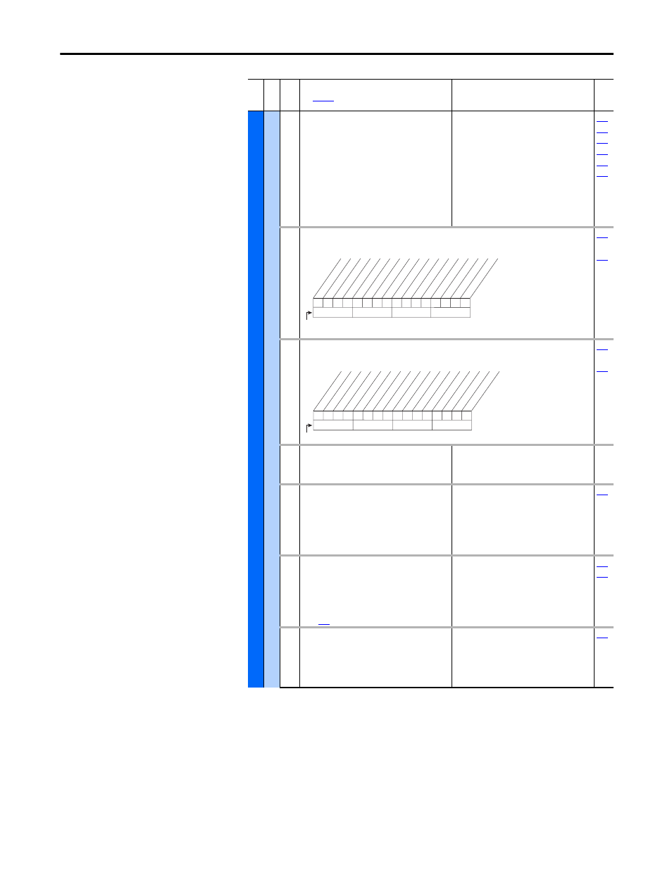
216 [Dig In Status]
Status of the digital inputs.
Read Only
…
217 [Dig Out Status]
Status of the digital outputs.
Read Only
…
218 [Drive Temp]
Present operating temperature of the drive
power section.
Default:
Min/Max:
Units:
Read Only
0.0/100.0%
0.1%
219 [Drive OL Count]
Accumulated percentage of drive overload.
Continuously operating the drive over 100% of its
rating will increase this value to 100% and cause
a drive fault or foldback depending on the
setting of [Drive OL Mode].
Default:
Min/Max:
Units:
Read Only
0.0/100.0%
0.1%
220 [Motor OL Count]
Accumulated percentage of motor overload.
Continuously operating the motor over 100% of
the motor overload setting will increase this
value to 100% and cause a drive fault. Refer to
page
Default:
Min/Max:
Units:
Read Only
0.0/100.0%
0.1%
221 [Mtr OL Trip Time]
Amount of time before a Drive Overload fault
(F64) occurs if the load condition remains
constant. A value of 99999 means that the drive
is operating under the overload level.
Default:
Min/Max:
Units:
Read Only
0/99999
1
Fil
e
Gr
oup
No
.
Parameter Name & Description
See
page 16
for symbol descriptions
Values
Rela
ted
0
0
0
0
0
0
x
x
0
0
0
0
0
0
x
x
10
0
1
2
3
4
5
6
7
8
9
11
12
13
14
15
1 = Input Present
0 = Input Not Present
x = Reserved
Bit #
Digital In1
Digital In2
Digital In3
Digital In4
Digital In5
Digital In6
In1 DL
ogRslt
(1)
In2 DL
ogRslt
(1)
In3 DL
ogRslt
(1)
In4 DL
ogRslt
(1)
In5 DL
ogRslt
(1)
In6 DL
ogRslt
(1)
(1)
Firmware 6.002 and later.
0
0
x
0
x
x
x
x
x
x
x
x
x
x
x
x
10
0
1
2
3
4
5
6
7
8
9
11
12
13
14
15
1 = Output Energized
0 = Output De-energized
x = Reserved
Bit #
Digital O
ut1
Digital O
ut2
Digital O
ut3