Motor requirements, Drive wiring, Motor requirements drive wiring – Rockwell Automation 20B PowerFlex 700 AC Drives Vector Control (v4.001 and up) User Manual
Page 148
148
Rockwell Automation Publication 20B-UM002G-EN-P - July 2014
Appendix D
Instructions for ATEX Approved Drives in Group II Category (2) G D Applications with ATEX Approved Motors
Motor Requirements
• The motor must be manufactured under the guidelines of the ATEX
directive 94/9/EC. It must be installed, operated, and maintained per the
motor manufacturer supplied instructions.
• Only motors with nameplates marked for use on an inverter power source,
and labeled for specific hazardous areas, can be used in hazardous areas on
inverter (variable frequency) power.
• When the motor is indicated for ATEX Group II Category 2 for use in gas
environments (Category 2G) the motor must be of flameproof
construction, EEx d (according to EN50018) or Ex d (according to
EN60079-1 or IEC60079-1). Group II motors are marked with a
temperature or a temperature code.
• When the motor is indicated for ATEX Group II Category 2 for use in
dust environments (Category 2D) the motor must be protected by an
enclosure (according to EN50281-1-1 or according to IEC61241-1: Ex
tD). Group II motors are marked with a temperature.
• The motor over temperature signal supplied to the drive must be a
normally closed contact (open during over temperature condition)
compatible with the drive’s digital (logic) input circuitry. If multiple
sensors are required in the motor, the connection at the drive must be the
resultant of all required contacts wired in series. Note that the drives are
available with either 24V DC or 115V AC input circuitry.
• Refer to all product markings for additional cautions that can apply.
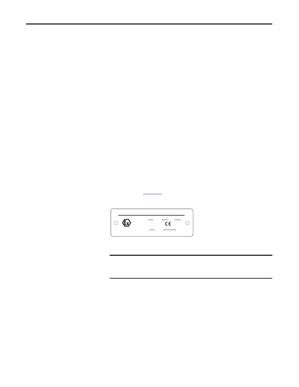
• Typical motor markings are contained on a motor certification nameplate
similar to
.
Figure 25 - Sample Motor Nameplate
Drive Wiring
The first input must be “Digital Input6/Hardware Enable” (terminal 32). The
second can be any other unused digital input between 1 and 5. Note that all
inputs are typically supplied in a “default” configuration to a function such as
Start and Stop. This can influence the input selected by the user for this function.
The following examples will assume Digital Input 5 (terminal 31) is being used as
the additional required input. The 2 input terminals must be wired in “parallel”
(jumper is acceptable) so each is monitoring the over temperature contacts.
Digital signal inputs are wired with respect to the digital input common. Refer to
the Installation Instructions regarding setup for either internal or external 24V
DC or external 115V AC logic power, depending on the type that is supplied in
your drive. Motor supplied contacts must have ratings compatible with the drive’s
input circuit ratings and applied voltage level.
FLAMEPROOF Exd ENCLOSURE
EExd I/IIB
Tamb
C to
C
II 2 G/D
I M2
Sira
ATEX
MFG. BY ROCKWELL AUTOMATION
0518
IMPORTANT
ATEX certification of this drive requires that 2 separate digital (logic) inputs be
configured to monitor a normally closed over temperature contact (or multiple
contacts wired in series) presented to the drive from the motor.