Rockwell Automation 20B PowerFlex 700 AC Drives Vector Control (v4.001 and up) User Manual
Page 40
40
Rockwell Automation Publication 20B-UM002G-EN-P - July 2014
Chapter 1
Programming and Parameters
DYNAMIC C
ONTROL
Stop/B
rak
e Mo
des
161
162
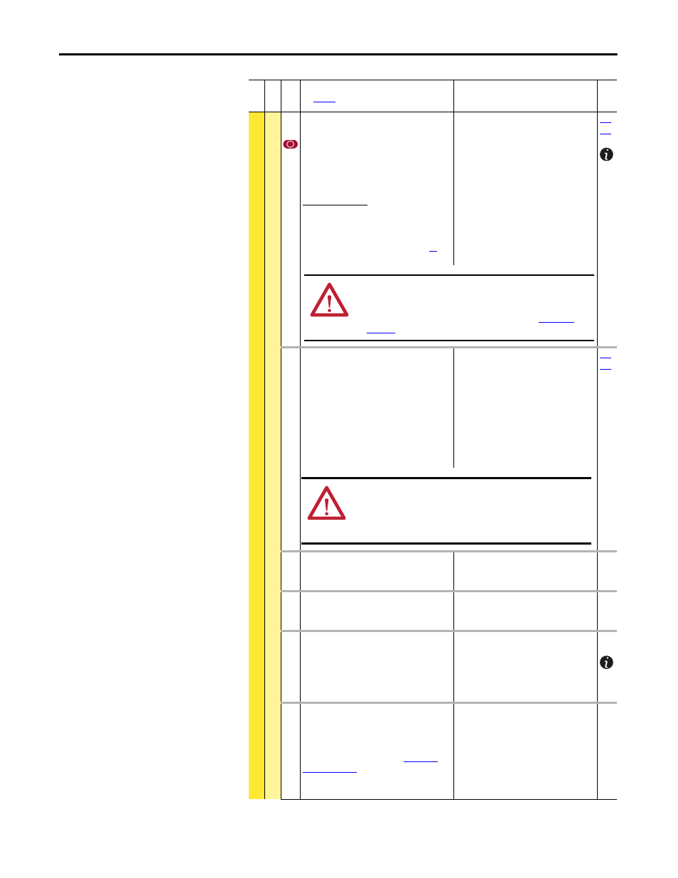
[Bus Reg Mode A]
[Bus Reg Mode B]
Sets the method and sequence of the DC bus
regulator voltage. Choices are dynamic brake,
frequency adjust or both. Sequence is
determined by programming or digital input to
the terminal block.
Dynamic Brake Setup
If a dynamic brake resistor is connected to the
drive, both of these parameters must be set to
either option 2, 3 or 4.
Refer to the Attention statement on page
important information on bus regulation.
Default:
Options:
1
4
0
1
2
3
4
“Adjust Freq”
“Both-Frq 1st”
“Disabled”
“Adjust Freq”
“Dynamic Brak”
“Both-DB 1st”
“Both-Frq 1st”
163 [DB Resistor Type]
Selects whether the internal or an external DB
resistor will be used.
Important: In Frame 0…2 drives, only one DB
resistor can be connected to the drive.
Connecting both an internal & external resistor
could cause damage.
If a dynamic brake resistor is connected to the
drive, [Bus Reg Mode A & B] must be set to either
option 2, 3 or 4.
Default:
Options:
2
0
1
2
“None”
“Internal Res”
“External Res”
“None”
164 [Bus Reg Kp]
Proportional gain for the bus regulator. Used to
adjust regulator response.
Default:
Min/Max:
Units:
1500
0/10000
1
165 [Bus Reg Kd]
Derivative gain for the bus regulator. Used to
control regulator overshoot.
Default:
Min/Max:
Units:
1000
0/10000
1
166 [Flux Braking]
Set to use an increase in the motor flux current to
increase the motor losses, and allow a faster
deceleration time when a chopper brake or
regenerative capability is not available. Can be
used as a stopping or fast deceleration method.
Default:
Options:
0
0
1
“Disabled”
“Disabled”
“Enabled”
452 [Stop Dwell Time]
Sets an adjustable delay time between detecting
zero speed and disabling the speed and torque
regulators, when responding to a stop command.
For more information, please see
Important: Consult industry and local codes
when setting the value of this parameter.
Default:
Min/Max:
Units:
0.00 Secs
0.00/60.00 Secs
0.01 Secs
Fil
e
Gr
oup
No
.
Parameter Name & Description
See
page 16
for symbol descriptions
Values
Rela
ted
ATTENTION: The drive does not offer protection for externally
mounted brake resistors. A risk of fire exists if external braking resistors
are not protected. External resistor packages must be self-protected
from over temperature or the protective circuit shown in
(or equivalent) must be supplied.
ATTENTION: Equipment damage can result if a drive mounted
(internal) resistor is installed and this parameter is set to “External Res”
or “None.” Thermal protection for the internal resistor will be disabled,
resulting in possible device damage. Also see ATTENTION statement in
parameter 161/162.