Rockwell Automation 20B PowerFlex 700 AC Drives Vector Control (v4.001 and up) User Manual
Page 65
Rockwell Automation Publication 20B-UM002G-EN-P - July 2014
65
Programming and Parameters
Chapter 1
IN
PUT
S &
O
U
TPUT
S
Digi
tal O
utpu
ts
380
384
388
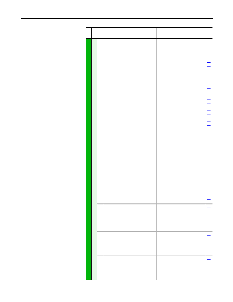
[Digital Out1 Sel]
(4)
[Digital Out2 Sel]
[Digital Out3 Sel]
Selects the drive status that will energize a (CRx)
output relay.
(1)
Any relay programmed as Fault or Alarm will
energize (pick up) when power is applied to drive
and deenergize (drop out) when a fault or alarm
exists. Relays selected for other functions will
energize only when that condition exists and will
deenergize when condition is removed.
(2)
Refer to Option Definitions on
.
(3)
Activation level is defined in [Dig Outx Level]
below.
(4)
When [TorqProve Cnfg] is set to “Enable,” [Digital
Out1 Sel] becomes the brake control and any other
selection will be ignored.
(5)
Firmware 6.002 & Later.
Default:
Options:
1
4
4
1
2
3
4
5
6
7
8
9
10
11
12
13
14
15
16
17
18
19
20
21-26
27
28
29
30
31
32
33
34
35
36
37
38
39
40
41
42-57
58
59
60
61
“Fault”
“Run”
“Run”
“Fault”
(1)
“Alarm”
(1)
“Ready”
“Run”
“Forward Run”
“Reverse Run”
“Auto Restart”
“Powerup Run”
“At Speed”
(2)
“At Freq”
(3)
“At Current”
(3)
“At Torque”
(3)
“At Temp”
(3)
“At Bus Volts”
(3)
“At PI Error”
(3)
“DC Braking”
“Curr Limit”
“Economize”
“Motor Overld”
“Power Loss”
“Input 1-6 Link”
“PI Enable”
“PI Hold”
“Drive Overload”
“Param Cntl”
(2)
”Mask 1 AND”
”Mask 1 OR”
”Prof At Pos”
”Prof Enabled”
”Prof Running”
”Prof Holding”
”Prof At Home”
”ProfComplete”
”Prof Homing”
”Prof Dwell”
”Prof Batch”
”Prof @ Step1-16”
“Manual Mode”
(5)
“Fast Braking”
(5)
“TrqPrv Brake”
(5)
“Speed Fdbk”
(5)
002
001
003
004
218
012
137
157
147
053
048
184
381
385
389
[Dig Out1 Level]
[Dig Out2 Level]
[Dig Out3 Level]
Sets the relay activation level for options 10-15 in
[Digital Outx Sel]. Units are assumed to match
the above selection (i.e. “At Freq” = Hz, “At
Torque” = Amps).
Default:
Min/Max:
Units:
0.0
0.0
0.0
0.0/819.2
0.1
382
386
390
[Dig Out1 OnTime]
[Dig Out2 OnTime]
[Dig Out3 OnTime]
Sets the “ON Delay” time for the digital outputs.
This is the time between the occurrence of a
condition and activation of the relay.
Default:
Min/Max:
Units:
0.00 Secs
0.00 Secs
0.00/600.00 Secs
0.01 Secs
383
387
391
[Dig Out1 OffTime]
[Dig Out2 OffTime]
[Dig Out3 OffTime]
Sets the “OFF Delay” time for the digital outputs.
This is the time between the disappearance of a
condition and de-activation of the relay.
Default:
Min/Max:
Units:
0.00 Secs
0.00 Secs
0.00/600.00 Secs
0.01 Secs
Fil
e
Gr
oup
No
.
Parameter Name & Description
See
page 16
for symbol descriptions
Values
Rela
ted