Rockwell Automation 20B PowerFlex 700 AC Drives Vector Control (v4.001 and up) User Manual
Page 64
64
Rockwell Automation Publication 20B-UM002G-EN-P - July 2014
Chapter 1
Programming and Parameters
INPUT
S &
OUTPUT
S
Digi
tal In
put
s
(15)
Adjust Voltage Select Inputs
(16)
Mixing selections 63-65 with 60-62 or 15-17 will
cause a type 2 alarm.
(17)
Firmware revision 10.001 and later.
411
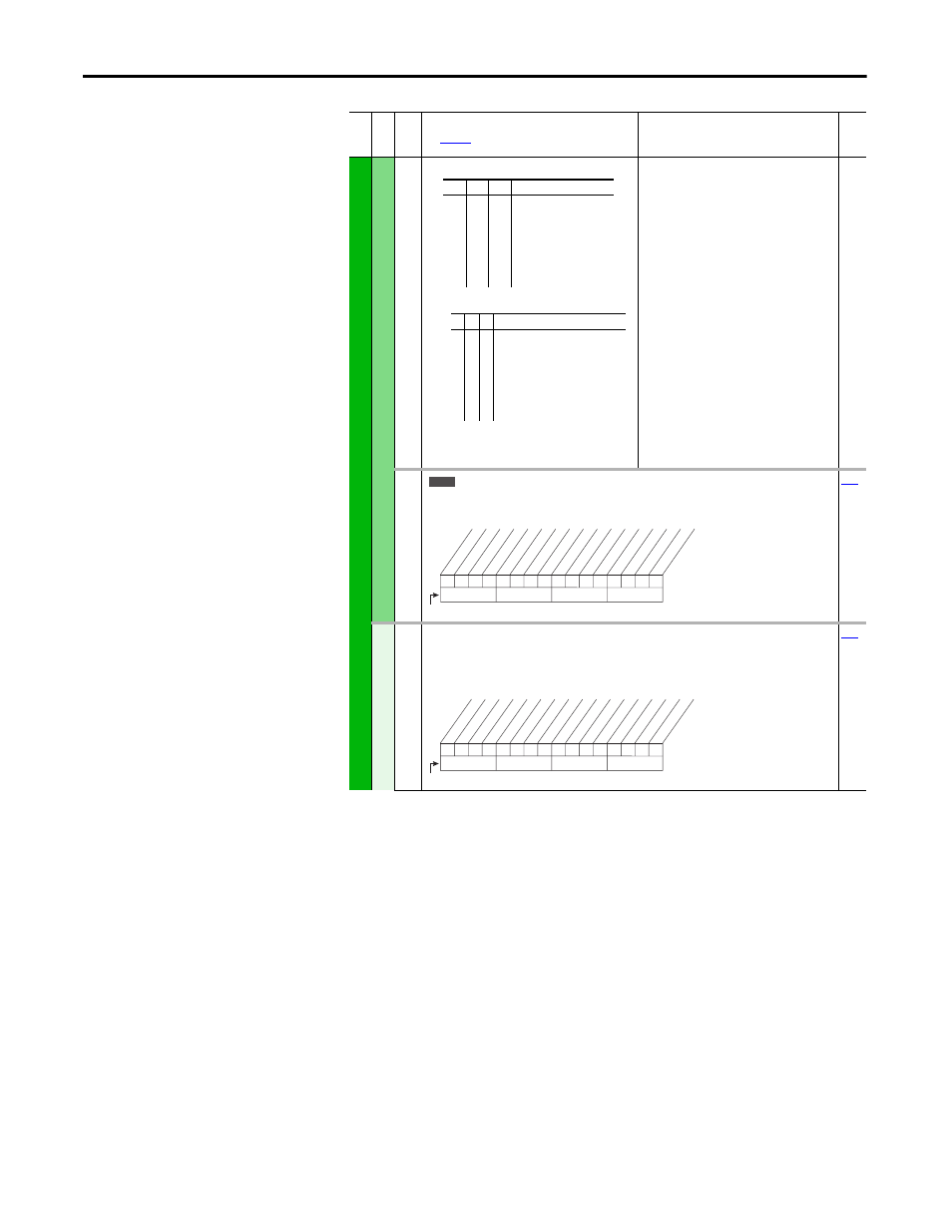
[DigIn DataLogic]
Provides data to the logical operations that will be done with the digital inputs when parameter
056 is set to option 9, “DigIn DatLog.”
D
igi
tal
O
u
tpu
ts
379 [Dig Out Setpt]
Sets the digital output value from a communication device.
Example: Set [Data In B1] to “379.” The first three bits of this value will determine the setting of
[Digital Outx Sel] which should be set to “30, Param Cntl.”
Fil
e
Gr
oup
No
.
Parameter Name & Description
See
page 16
for symbol descriptions
Values
Rela
ted
3
2
1
AdjV Sel
0
0
0
0
1
1
1
1
0
0
1
1
0
0
1
1
0
1
0
1
0
1
0
1
Adj Volt Sel
Adj Volt Preset1
Adj Volt Preset2
Adj Volt Preset3
Adj Volt Preset4
Adj Volt Preset5
Adj Volt Preset6
Adj Volt Preset7
3
2
1
AdjV Sel
0
0
0
0
1
1
1
1
0
0
1
1
0
0
1
1
0
1
0
1
0
1
0
1
Adj Volt Sel & Speed ref A Sel
Adj Volt Preset1 & Speed Ref B Sel
Adj Volt Preset2 & Speed Preset 2
Adj Volt Preset3 & Speed Preset 3
Adj Volt Preset4 & Speed Preset 4
Adj Volt Preset5 & Speed Preset 5
Adj Volt Preset6 & Speed Preset 6
Adj Volt Preset7 & Speed Preset 7
v6
0
0
0
0
0
0
x
x
0
0
0
0
0
0
x
x
10
0
1
2
3
4
5
6
7
8
9
11
12
13
14
15
1 = Logical 1
0 = Logical 0
x = Reserved
Bit #
In1 AND
da
ta
In2 AND
da
ta
In3 AND
da
ta
In4 AND
da
ta
In5 AND
da
ta
In6 AND
da
ta
In1 ORda
ta
In2 ORda
ta
In3 ORda
ta
In4 ORda
ta
In5 ORda
ta
In6 ORda
ta
0
0
x
0
x
x
x
x
x
x
x
x
x
x
x
x
10
0
1
2
3
4
5
6
7
8
9
11
12
13
14
15
1 = Output Energized
0 = Output De-energized
x = Reserved
Bit #
Digital O
ut1
Digital O
ut2
Digital O
ut3