Process pid, Pi enable – Rockwell Automation 20B PowerFlex 700 AC Drives Vector Control (v4.001 and up) User Manual
Page 134
134
Rockwell Automation Publication 20B-UM002G-EN-P - July 2014
Appendix C
Application Notes
Process PID
The internal PI function of the PowerFlex 700 provides closed loop process
control with proportional and integral control action. The function is designed
for use in applications that require simple control of a process without external
control devices. The PI function allows the microprocessor of the drive to follow
a single process control loop.
The PI function reads a process variable input to the drive and compares it to a
desired setpoint stored in the drive. The algorithm will then adjust the output of
the PI regulator, changing drive output frequency to try and make the process
variable equal the setpoint.
It can operate as trim mode by summing the PI loop output with a master speed
reference.
Or, it can operate as control mode by supplying the entire speed reference. This
method is identified as “exclusive mode.”
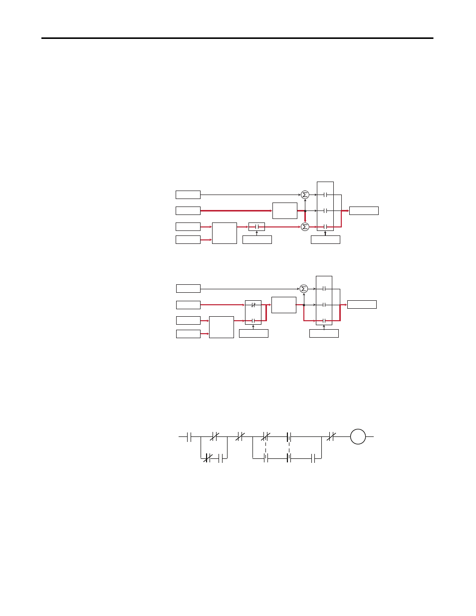
PI Enable
The output of the PI loop can be turned on (enabled) or turned off (disabled).
This control allows the user to determine when the PI loop is providing part or
all of the commanded speed. The logic for enabling the PI loop is shown below.
The drive must be running for the PI loop to be enabled. The loop will be
disabled when the drive is ramping to a stop (unless “Stop Mode” is configured in
[PI Configuration]), jogging or the signal loss protection for the analog input(s)
is sensing a loss of signal.
If a digital input has been configured to “PI Enable,” two events are required to
enable the loop: the digital input must be closed AND bit 0 of the PI Control
parameter must be = 1.
+
Spd Cmd
Process PI
Controller
Linear Ramp
& S-Curve
+
+
+
PI Enabled
Speed Control
Spd Ref
PI Ref
PI Fbk
Slip Adder
Open
Loop
Slip
Comp
Process
PI
Spd Cmd
Process PI
Controller
Linear Ramp
& S-Curve
+
+
PI Enabled
Speed Control
Spd Ref
PI Ref
PI Fbk
Slip Adder
Open
Loop
Slip
Comp
Process
PI
Drive
Running
Drive
Ramping
to Stop
Drive
Jogging
Bit 0 of
[PI Control] = 1
(enabled)
[PI Configuration]
Signal Loss
The Configured
Digital Input
is Closed
A Digital Input
is Configured
to PI Enable
"Enabled" Status
Digital Input
is Reflected
in [PI Status]
Bit 0 = 1
The PI Loop
is Enabled
Bit 0
Bit 6