INFICON MDC-260 Thin Film Deposition Controller User Manual
Page 188
MDC-260 DEPOSITION CONTROLLER
REPAIR AND MAINTENANCE
12-2
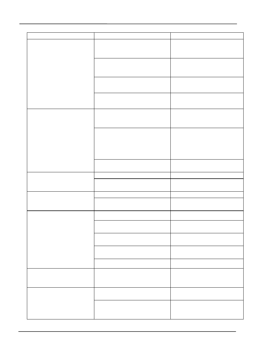
Symptom Possible
Cause Remedy
a) Line voltage selection wheel
is not installed to agree with line
voltage being used.
a) Change line voltage
selection. Refer to Section
8.3.3
b) Incorrect fuse size or type.
b) Replace with correct fuse
size (or type). See Section
8.3.3
c) Shorted rectifiers in power
supply area.
c) Return unit to manufacturer
for repair.
Unit blows line fuse.
d) Shorted transformer or filter
capacitor.
d) Return unit to manufacturer
for repair.
a) Blown fuse.
a) Replace with correct fuse
size (or type). See Section
8.3.3
b) Loose connections between
LCD and main board.
b) Check and secure LCD
backlight connector to
main board J6. Check and
secure LCD data lines
cable to main board J12.
Front Panel display never
illuminates.
c) Faulty clock generator (High
Speed Clock)
c) Return unit to manufacturer
for repair.
a) Contrast level is set too low.
a) Adjust contrast (Sec 4.1.6)
LCD display shows a blank
blue screen.
b) Bad LCD display.
b) Return unit to manufacturer
for repair.
a) Contrast level is set too high.
a) Adjust contrast (Sec 4.1.6)
LCD display shows a bright
“white” screen.
b) Bad LCD display.
b) Return unit to manufacturer
for repair.
a) Defective cable or cables.
a) Replace cable(s)
b) Defective or overloaded
sensor crystal.
b) Replace crystal with a new
one.
c) Oscillator unit connected in
the wrong direction.
c) Reverse the connections.
d) Bad Oscillator unit.
d) Replace with a new
oscillator.
“Crystal Failure” message
flashes with selected sensor
properly connected.
e) Improper cable length
e)
No control voltage while
monitoring output of
selected Source.
a) Improperly wired cable, or
shorted wires.
a) Verify the cable connection
against Figure 13-1. Also,
check for electrical shorts.
a) Defective membrane keys b)
Contact
manufacturer.
Front panel control keys
non- functional.
b) Loose connections between
the membrane keys and the
main board.
b) Check and secure
membrane connector to
main board J10.