Code #23: receive input setup, Code #24: send output setup, Code #23: receive input setup -30 – INFICON MDC-260 Thin Film Deposition Controller User Manual
Page 168: Code #24: send output setup -30
MDC-260 DEPOSITION CONTROLLER
COMPUTER INTERFACE
11-30
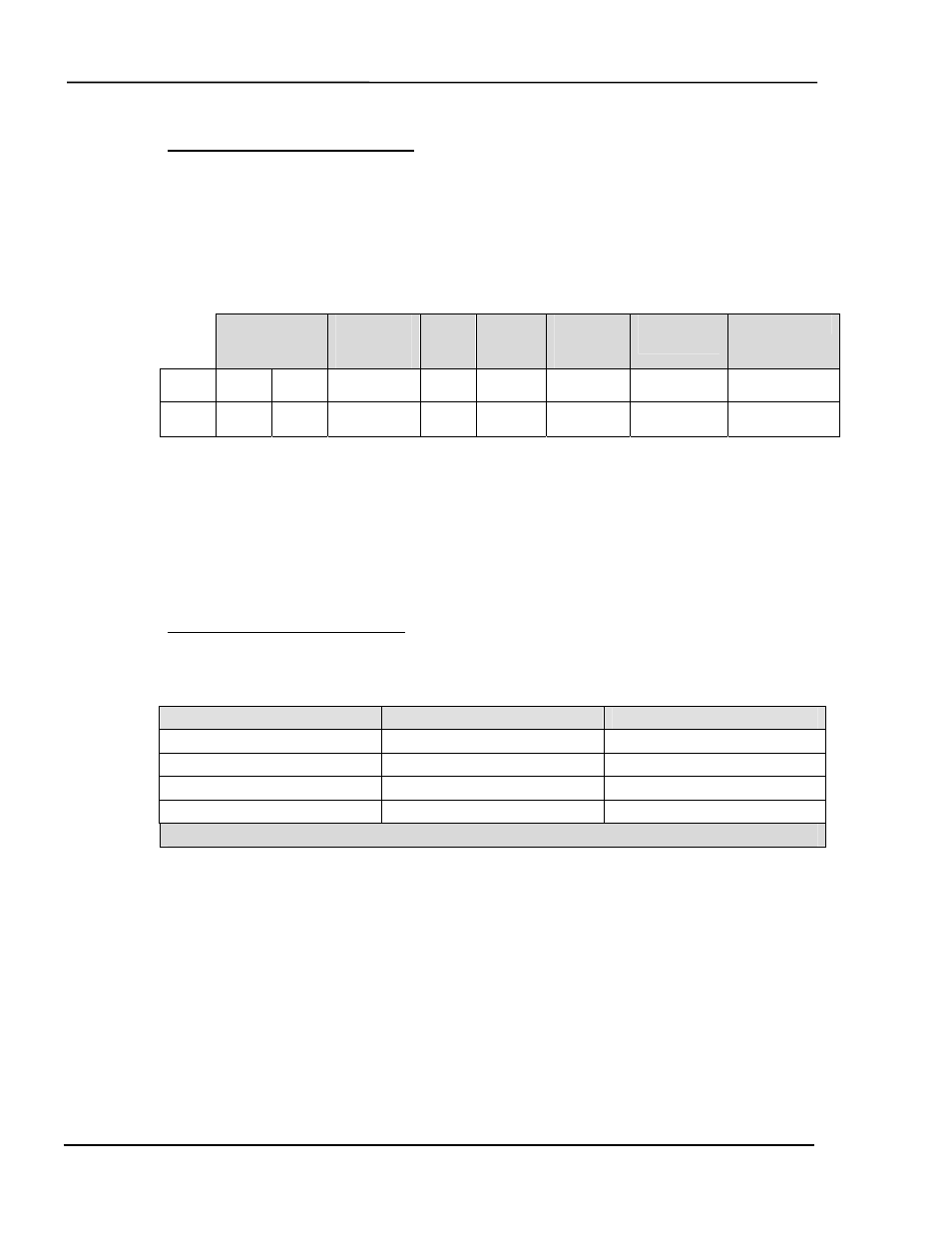
Code #23: Receive Input Setup
Description:
Instructs the controller to enter the incoming Input parameters for
Input #N into memory. Use the table from Code #22 to construct a message to set
the parameters for Input #N to your desired settings.
Format/Example:
• To re-program Input #N with custom parameters, transmit:
Header
Interface
Address
Inst.
Code
Length
Input #N
(1-8)
20 Data
Bytes
Checksum
Dec
255 254
1
22
21
4 (data)
(checksum)
Hex
FF FE
01
16
15
04 (data)
(checksum)
(data):
The 20 data bytes represent the configuration parameters the selected
Input.
(checksum):
The checksum from the instruction code through the last data byte.
Response:
• The controller will respond with the normal transmission receipt.
Code #24: Send Output Setup
Description:
Instructs the controller to send the Output parameter list for Output
#N. A description of the Output parameter list is as follows:
Parameter Name
Length (bytes)
Allowable Range
Name
16
All ASCII Characters
Type *
2
0 – 65535 (LSB first)
Condition String **
24
! | & ( )
Output Pin#
1
2-9
Total: 43 Data Bytes
* The Type parameter defines whether the input is undefined, user defined, or
internally defined. 0 = Undefined 65,535 = user defined. All other values
indicated internally defined inputs created by the MDC for source pocket and
sensor crystal position control. When clearing an input you must set the Type = 0
(00 hex). When defining an input you must set the type = 65535 (FF hex).
Internal types should only be set by the MDC.
** The condition string is described in the program I/O section of the manual.
The allowable characters are ! | & ( ). The individual conditions are represented
by numbers. The conditions are 1, 2, or 3 bytes each. The first byte is the
condition number. The second and third byte, if any, are the sub-condition
number. The allowable conditions are listed in the table following the example.