Connecting and wiring the modules, Rmh module connections, Watlow ez-zone – Watlow EZ-ZONE RMH User Manual
Page 37: Rmh module, Chapter 2 install and wire
Watlow EZ-ZONE
®
RMH Module
•
34
•
Chapter 2 Install and Wire
Connecting and Wiring the Modules
RMH Module Connections
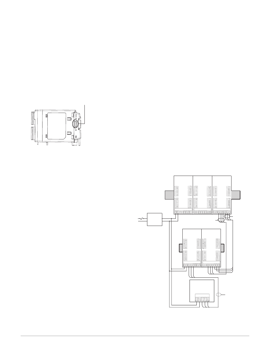
The RMH module can be installed as a stand-alone
limit controller or can be interconnected on the DIN
rail as shown below with other RM family modules.
When modules are connected together as shown,
power and communications are shared between mod-
ules over the modular backplane interconnection.
Therefore, bringing the necessary power and commu-
nications wiring to any one connector in slot C is suf-
ficient. The modular backplane interconnect comes
standard with every module ordered and is generic
in nature, meaning any RM modules shown below on
RM Controller
Module
RM High Density
Module
RM Access
Module
RMCxxxxxxxxxAxx RMHx-xxxx-xAxx
RMAx-xxxx-xxx
Slot C
Slot C
Slot C
_
_
_
_
_
_
_
_
Slot A
Slot A
_
_
_
_
_
_
_
_
_
_
_
_
_
_
_
_
Slot D
_
_
_
_
_
_
_
_
Slot D
_
_
_
_
_
_
_
_
Slot D
Slot A
_
_
_
_
_
_
_
_
_
_
_
_
_
_
_
_
Slot E
CE
CD
CF
99
98
RUI
EZKB-_ A _ _- _ _ _ _
RM Controller
Module
RM Expansion
Module
RMCxxxxxxxxxAxx
_
_
_
_
_
_
_
_
Slot A
_
_
_
_
_
_
_
_
Slot D
_
_
_
_
_
_
_
_
Slot E
_
_
_
_
_
_
_
_
Slot B
RMEx-xxxx-xxxx
Slot C
_
_
_
_
_
_
_
_
Slot A
_
_
_
_
_
_
_
_
Slot D
_
_
_
_
_
_
_
_
Slot E
_
_
_
_
_
_
_
_
Slot B
Split Rail Configuration
Standard Bus
Address 4
Standard Bus
Address 5
Standard Bus
Address 1
Standard Bus
Address 2
Standard Bus
Address 3
Standard Bus
Inter-module
Bus
CY
CX
CZ
CE
CD
CF
99
98
Slot B
_
_
_
_
_
_
_
_
Slot B
_
_
_
_
_
_
_
_
Slot E
_
_
_
_
_
_
_
_
Slot E
_
_
_
_
_
_
_
_
Slot B
_
_
_
_
_
_
_
_
CY
CX
CZ
CE
CD
CF
99
98
CY
CX
CZ
CE
CD
CF
99
98
CY
CX
CZ
CE
CD
CF
99
98
CY
CX
CZ
CE
CD
CF
99
98
Slot C
Power Supply
Low Voltage
Class 2
Standard Bus
Modular backplane interconnect
the DIN rail can use it.
Notice in the split rail system diagram that a
single power supply is being used across both DIN
rails. One notable consideration when designing the
hardware layout would be the available power sup-
plied and the loading affect of all of the modules
used. Watlow provides three options for power sup-
plies listed below:
1. 90-264 Vac to 24Vdc @ 31 watts (Part #: 0847-
0299-0000)
2. 90-264 Vac to 24Vdc @ 60 watts (Part #: 0847-
0300-0000)
3. 90-264 Vac to 24Vdc @ 91 watts (Part #: 0847-
0301-0000)
With regards to the modular loading affect, maxi-
mum power for each RM module is listed below:
1. RMCxxxxxxxxxxxx @ 7 watts / 14VA
2. RMEx-xxxx-xxxx @ 7 watts / 14VA
3. RMAx-xxxx-xxxx @ 4 watts / 9VA
4. RMLx-xxxx-xxxx @ 7 watts / 14VA
5. RMHx-xxxx-xxxx @ 7 watts / 14VA
6. RMSx-xxxx-xxxx @ 7 watts / 14VA
So, in the split rail system diagram, the maximum
current draw on the supply would be 38 Watts.
- 2 RMC modules consumes 14W
- 1 RMH module consumes 7W
- 1 RME modules consumes 7W
- 1 RMA module consumes 4W
- 1 Remote User Interface consumes 6W
With this power requirement (38 watts) the second or
third power supply could be used.
Another hardware configuration scenario that could
present itself (graphic not shown) would be a con-
figuration that requires more than one supply. Lets
make some assumptions pertaining to the split rail
system diagram shown below. The power supply
used is the 91W supply. The top DIN rail now has
the following modules:
- 2 RMC modules consumes 14W
- 1 RMA consumes 4W
- 11 RME modules consumes 77W
- 2 RMH modules consumes 14W
As can now be seen, the total power requirement
exceeds 91W. In this case, another power supply
would be required. To incorporate another supply in
this system simply disconnect pins 99 and 98 on the
remote DIN rail and connect another appropriately
sized power supply for the remote modules to those
same pins.
When using a split rail configuration ensure that
the interconnections for the Inter-module Bus and
Standard Bus do not exceed 200 feet. Standard Bus
and the Inter-module Buses are different protocols
and both are required for split rail configurations.
Without having both connected communications be-
tween modules would not be possible.
Note:
Unit is not provided with a disconnect, use of an
external disconnect is required. It should be located
in close proximity to the unit and be labeled as the
disconnect for the unit.