Tri-process/retransmit outputs 1-3, 7-9, L_ k_ l_ l_ k_ l, Watlow ez-zone – Watlow EZ-ZONE RMH User Manual
Page 32: Rmh module, Chapter 2 install and wire, Rmh part # digit 7, 8 is l, Rmh part # digit 7, 8 is f
Watlow EZ-ZONE
®
RMH Module
•
29
•
Chapter 2 Install and Wire
Warning:
ç
Use National Electric (NEC) or other
country-specific standard wiring and
safety practices when wiring and
connecting this controller to a power
source and to electrical sensors or pe-
ripheral devices. Failure to do so may
result in damage to equipment and
property, and/or injury or loss of life.
Note:
Maximum wire size termination and
torque rating:
• 0.0507 to 3.30 mm2 (30 to 12 AWG)
single-wire termination or two 1.31
mm2 (16 AWG)
• 0.8 Nm (7.0 in-lb.) torque
Note:
Adjacent terminals may be labeled
differently, depending on the model
number.
Note:
To prevent damage to the controller,
do not connect wires to unused ter-
minals.
Note:
Maintain electrical isolation between
digital input-outputs, switched dc/open
collector outputs and process outputs
to prevent ground loops.
Warning:
ç
Explosion Hazard – Substitution of
component may impair suitability for
CLASS I, DIVISION 2.
Warning:
ç
Explosion Hazard - Do not disconnect
while the circuit is live or unless the
area is known to be free of ignitable
concentrations of flammable sub-
stances.
Suppressor Note:
Switching pilot duty inductive loads
(relay coils, solenoids, etc .) with the
mechanical relay, solid state relay or
open collector output options requires
use of an R .C . suppressor for AC load or
a diode for a DC load .
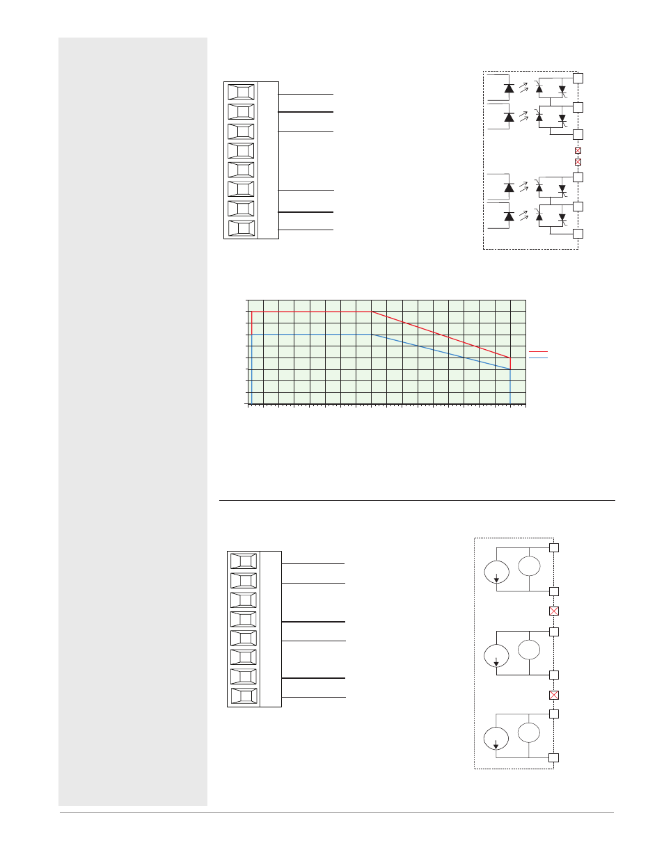
Quad 2A SSR Outputs 1-4, 7-10
RMH Part # Digit 7, 8 is L
normally open
common
L_
K_
L_
L_
K_
L_
Slot D, E
normally open
normally open
common
normally open
• 2 A at 20 to 264VÅ (ac)
maximum resistive load
• 50 VA 120/240VÅ (ac) pilot
duty
• Optical isolation, without
contact suppression
• maximum off state leak-
age of 105 microamperes
• Output does not supply
power.
• Do not use on dc loads.
• N.O., COM, N.O wiring
(shared common) between
each set of outputs.
• See Quencharc note.
K_
L_
L_
Normally Open
Normally Open
Common
K_
L_
L_
Normally Open
Normally Open
Common
Not Used
Not Used
Quad 2 Amp SSR Derating Curve
All Outputs 100% Duty Cycle
Amps per Output
Ambient Temperature (
o
C)
0
-20
15
10
5
0
-5
-10
-15
20
0.25
0.50
2.25
0.75
1.0
1.25
1.50
1.75
2.00
25
30
35
40
45
50
55
60
65
70
1 Quad SSR
Multiple Quad SSR Cards
Note:
Each of the four SSR outputs has internal circuitry that will protect it from over
heating. Outputs may be disabled (shut off) automatically if internal temperatures
exceed those listed in the graph above. After the output temperature drops approxi-
mately 10 °C the outputs will once again be enabled for operation.
Tri-Process/Retransmit Outputs 1-3, 7-9
RMH Part # Digit 7, 8 is F
volts or current -
volts +/current +
F_
H_
Slot A, B, D, E
F_
H_
F_
H_
volts or current -
volts +/current +
volts or current -
volts +/current +
• 0 to 20 mA into 400Ω
maximum load
• 0 to 10VÎ (dc) into 4
kΩ minimum load
• Outputs are scalable
• Output supplies pow-
er
• Each output can be
independently set for
voltage or current.
• Output may be used
as retransmit or con-
trol.
negative
volts +
or
current +
0 to 10 V
F_
H_
0 to 10 V
F_
H_
0 to 10 V
0 to 20 mA
F_
H_
Not Used
Not Used
volts +
or
current +
volts +
or
current +
negative
negative
0 to 20 mA
0 to 20 mA