Module orientation – Watlow EZ-ZONE RMH User Manual
Page 11
Watlow EZ-ZONE
®
RMH Module
•
8
•
Chapter 1 Overview
RMH
Controller
RMC
Controller
RMC
Controller
RMH
Controller
RM
Access
Power
Supply
Slot C
Slot C
Slot C
Slot C
Slot C
Slot
E
OIT
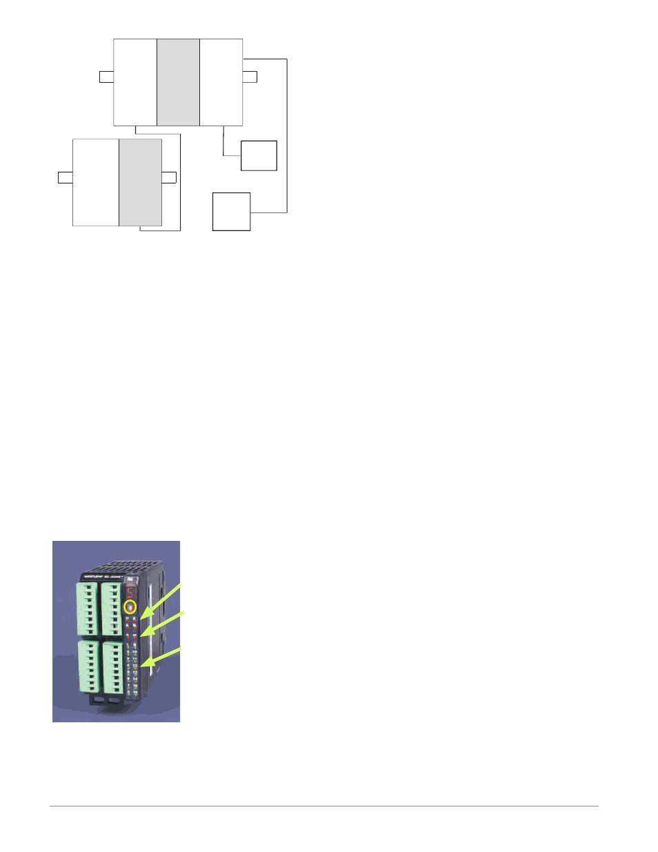
Module Orientation
The picture that follows represents one of several dif-
ferent RM modules. All of them will have four slots
on the face (slot A, B, D, and E) and one on the bot-
tom (slot C) not shown. All of these slots are not al-
ways used on all modules. On the face of the module
there is a button (yellow circle) under the Zone ad-
dress ([5]). When pushed and held it has the following
functions:
1. For any module, push and hold for ~ 2 seconds to
change the Zone address
2. When a module is equipped with the Modbus pro-
tocol (RMxxxxxxxxxx1xx) pushing and holding this
button for ~ 6 seconds the LED display will return
[P]
for protocol. Releasing the button and then
pushing it again (within 6 seconds) the display
will toggle between [N] (Modbus) and [S] (Standard
Bus). Valid addresses for Modbus and Standard
bus range from 1 -16 ([1] - [9], [a] is 10, [b] is 11, [C]
is 12, [d] is 13, [e] is 14, [f] is 15, and [h] is 16). The
RMA (Access) module is shipped at address [j] or
17 and is the only module that can have its address
set above 16.
A
D
E
B
Module Status (Slot A,
B, D, or E)
Protocol (Standard Bus -
red or Modbus - green)
Module outputs 1
through 16, all may or
may not be used depend-
ing on module type