Dead band, Variable time base, Pid control – Watlow EZ-ZONE RMH User Manual
Page 109
Watlow EZ-ZONE
®
RMH Module
•
106
•
Chapter 6 Features
Time
Temperature
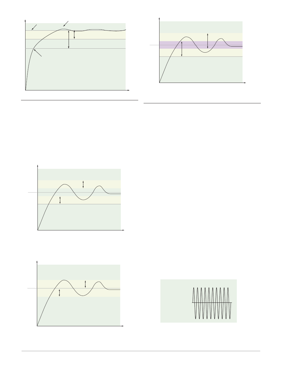
PID Control
Set Point
Reduced Overshoot
Proportional Band
Proportional Band x 2
Heating Slows
Dead Band
In a PID application the dead bands above and below
the set point can save an application’s energy and
wear by maintaining process temperature within ac-
ceptable ranges.
Proportional action ceases when the process value
is within the dead band. Integral action continues to
bring the process temperature to the set point.
Using a positive dead band value keeps the two
systems from fighting each other.
Time
Temperature
Positive Dead Band
Set Point
Heat Output Active
Cool Output Active
When the dead band value is zero, the heat-
ing output activates when the temperature drops be-
low the set point, and the cooling output switches on
when the temperature exceeds the set point.
Time
Temperature
Zero Dead Band
Set Point
Heat Output Active
Cool Output Active
When the dead band value is a negative val-
ue, both heating and cooling outputs are active when
the temperature is near the set point.
Time
Temperature
Negative Dead Band
Set Point
Heat Output Active
Cool Output Active
Adjust the dead band with Dead Band [``db]
(Operations Page, Loop Menu).
Variable Time Base
Variable time base is the preferred method for con-
trolling a resistive load, providing a very short time
base for longer heater life. Unlike phase-angle firing,
variable-time-base switching does not limit the cur-
rent and voltage applied to the heater.
With variable time base outputs, the PID algo-
rithm calculates an output between 0 and 100%, the
output is distributed at a minimum of three ac line
cycles. For each grouping of ac line cycles, the con-
troller decides whether the power should be on or
off. There is no fixed cycle time since the decision is
made for each group of cycles. When used in conjunc-
tion with a zero cross (burst fire) device, such as a
solid-state power controller, switching is done only at
the zero cross of the ac line, which helps reduce elec-
trical noise (RFI).
Variable time base should be used with solid-state
power controllers, such as a solid-state relay (SSR)
or silicon controlled rectifier (SCR) power controller.
Do not use a variable time base output for control-
ling electromechanical relays, mercury displacement
relays, inductive loads or heaters with unusual resis-
tance characteristics.
The combination of variable time base output and
a solid-state relay can inexpensively approach the ef-
fect of analog, phase-angle fired control.
Select the AC Line Frequency [AC;LF] (Setup Page,
Global Menu), 50 or 60 Hz.
100 percent output
10 ON, 0 OFF