Process inputs 1 through 16, Digital inputs 1 through 12 – Watlow EZ-ZONE RMH User Manual
Page 29
Warning:
ç
Use National Electric (NEC) or other
country-specific standard wiring and
safety practices when wiring and
connecting this controller to a power
source and to electrical sensors or pe-
ripheral devices. Failure to do so may
result in damage to equipment and
property, and/or injury or loss of life.
Note:
Maximum wire size termination and
torque rating:
• 0.0507 to 3.30 mm2 (30 to 12 AWG)
single-wire termination or two 1.31
mm2 (16 AWG)
• 0.8 Nm (7.0 in-lb.) torque
Note:
Adjacent terminals may be labeled
differently, depending on the model
number.
Note:
To prevent damage to the controller,
do not connect wires to unused ter-
minals.
Note:
Maintain electrical isolation between
digital input-outputs, switched dc/open
collector outputs and process outputs
to prevent ground loops.
Warning:
ç
Explosion Hazard – Substitution of
component may impair suitability for
CLASS I, DIVISION 2.
Warning:
ç
Explosion Hazard - Do not disconnect
while the circuit is live or unless the
area is known to be free of ignitable
concentrations of flammable sub-
stances.
Watlow EZ-ZONE
®
RMH Module
•
26
•
Chapter 2 Install and Wire
Suppressor Note:
Switching pilot duty inductive loads
(relay coils, solenoids, etc .) with the
mechanical relay, solid state relay or
open collector output options requires
use of an R .C . suppressor for AC load or
a diode for a DC load .
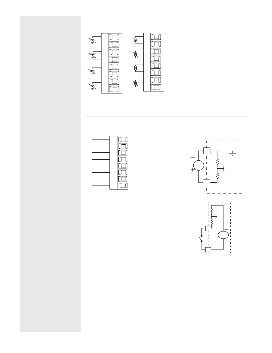
Process Inputs 1 through 16
RMH Part # Digit 5, 6, 7, 8 is 1
-
+
-
+
-
+
-
+
S_
R_
S_
R_
S_
R_
S_
R_
Slot A, B, D, E
-
+
-
+
-
+
-
+
S_
R_
S_
R_
S_
R_
S_
R_
Slot A, B, D, E
• 0 to 20 mA @ 100 Ω input imped-
ance
• 0 to 10V
Î
(dc) @ 20 kΩ input imped-
ance
• 0 to 50 mV
Î
(dc) @ 20 MΩ input im-
pedance
• scalable
Slot 1:
RMHx-(1)xxx-xxxx
(Inputs 1 to 4)
Slot 2:
RMHx-x(1)xx-xxxx
(Inputs 5 to 8)
Slot 3:
RMHx-xx(1)x-xxxx
(Inputs 9 to 12)
Slot 4:
RMHx-xxx(1)-xxxx
(Inputs 13 to 16)
Digital Inputs 1 through 12
RMH Part # Digit 7, 8 is C
Common
DC Input
B_
D_
D_
D_
D_
D_
D_
Z_
Slot D, E
Supply
DC Input
DC Input
DC Input
DC Input
DC Input
Internal
Digital Input Event
Conditions
• Voltage
- Input inactive when <
2V
- Input active when >
3V
• Dry Contact
- Input inactive when >
100KΩ
- Input active when <
50Ω
• Six user configurable
digital inputs/outputs
per slot
- Slot D DI 1 - 6
RMHx-xx(C) xx-xxxx
- Slot E DI 7 - 12
RMHx-xxx(C)-xxxx
Voltage Input
common
Vdc
D
_
B
_
Dry Contact
24 Vdc
_
Z
_
D