Open collector wiring example using do 1-12 – Watlow EZ-ZONE RMH User Manual
Page 31
Warning:
ç
Use National Electric (NEC) or other
country-specific standard wiring and
safety practices when wiring and
connecting this controller to a power
source and to electrical sensors or pe-
ripheral devices. Failure to do so may
result in damage to equipment and
property, and/or injury or loss of life.
Note:
Maximum wire size termination and
torque rating:
• 0.0507 to 3.30 mm2 (30 to 12 AWG)
single-wire termination or two 1.31
mm2 (16 AWG)
• 0.8 Nm (7.0 in-lb.) torque
Note:
Adjacent terminals may be labeled
differently, depending on the model
number.
Note:
To prevent damage to the controller,
do not connect wires to unused ter-
minals.
Note:
Maintain electrical isolation between
digital input-outputs, switched dc/open
collector outputs and process outputs
to prevent ground loops.
Warning:
ç
Explosion Hazard – Substitution of
component may impair suitability for
CLASS I, DIVISION 2.
Warning:
ç
Explosion Hazard - Do not disconnect
while the circuit is live or unless the
area is known to be free of ignitable
concentrations of flammable sub-
stances.
Watlow EZ-ZONE
®
RMH Module
•
28
•
Chapter 2 Install and Wire
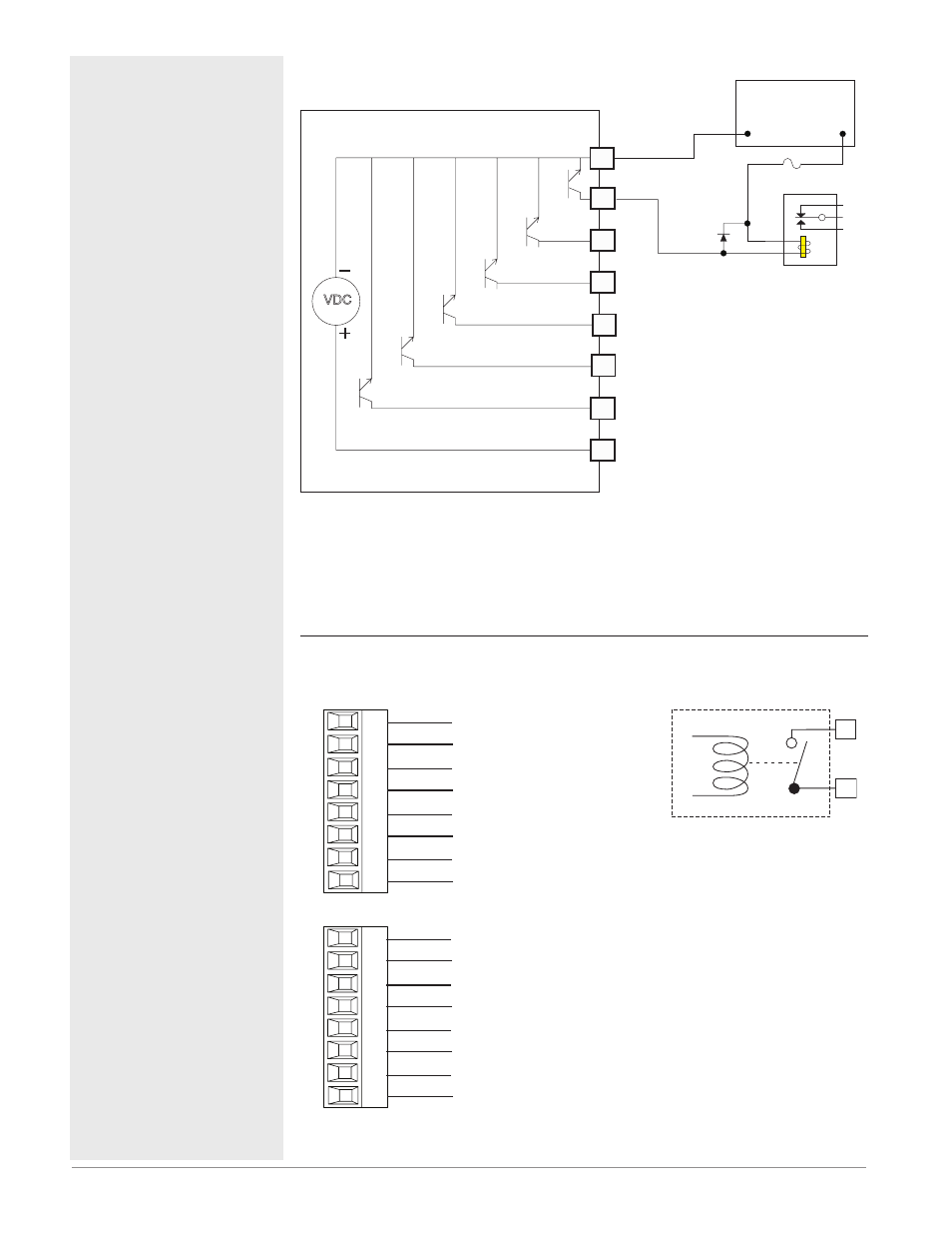
Open Collector Wiring Example Using DO 1-12
VDC
Collector Outputs
Internal Circuitry
Power Supply
5 to 32 VDC
Relay
+
-
Common
Internal Supply
Diode
Fuse
An example fuse is
Bussmann AGC-1 1/2
B_
Z_
D_
D_
D_
D_
D_
D_
As an open collector output (see graphic below), use an external power sup-
ply with the negative wired to B_, the positive to the coil of a pilot mechani-
cal relay and the other side of the coil wired to the output of choice (D_).
Each open collector output can sink 1.5 A with the total for all open collector
outputs not exceeding 8 amperes. Ensure that a kickback diode is reversed
wired across the relay coil to prevent damage to the internal transistor.
Output 1 - 4 and 7 - 10 Mechanical Relay, Form A
RMH Part # Digit 7, 8 is J
normally open
common
L1
K1
L2
K2
L3
K3
L4
K4
Slot D
normally open
common
normally open
common
normally open
common
normally open
common
L7
K7
L8
K8
L9
K9
L10
K10
Slot E
normally open
common
normally open
common
normally open
common
• 5 A at 240VÅ (ac) or 30VÎ
(dc) maximum resistive
load
• 20 mA at 24V minimum
load
• 125 VA pilot duty @
120/240VÅ (ac), 25 VA at
24VÅ (ac)
• 100,000 cycles at rated load
• Output does not supply
power.
• for use with ac or dc
See Quencharc note.
- Slot D Outputs 1 - 6
RMHx-xx(J)x-xxxx
- Slot E Outputs 7 - 10
RMHx-xxx(J)-xxxx
Mechanical Relay Form A
L_
K_
Internal Circuitry