Filter time constant, Sensor selection, Set point low limit and high limit – Watlow EZ-ZONE RMH User Manual
Page 105: Scale high and scale low, Range high and range low
Watlow EZ-ZONE
®
RMH Module
•
102
•
Chapter 6 Features
Calibration Menu) for this input to the offset val-
ue.
5. Check the Electrical Measurement to see whether
it now matches the resistance. If it doesn’t match,
adjust Electrical Offset again.
6. Measure the high source resistance to ensure it
is accurate. Connect the high source resistance to
the input.
7. Read the value of Electrical Measurement for
that input.
8. Calculate the gain value by dividing the low
source signal by this value.
9. Set Electrical Slope [ELi;S] (Factory Page, Cali-
bration Menu) for this input to the calculated
gain value.
10. Check the Electrical Measurement to see wheth-
er it now matches the signal. If it doesn’t match,
adjust Electrical Slope again.
Set Electrical Offset to 0 and Electrical Slope to 1 to
restore factory calibration.
Filter Time Constant
Filtering smoothes an input signal by applying a
first-order filter time constant to the signal. Filter-
ing the displayed value makes it easier to monitor.
Filtering the signal may improve the performance of
PID control in a noisy or very dynamic system.
Adjust the filter time interval with Filter Time
[`FiL]
(Setup Page, Analog Input Menu). Example:
With a filter value of 0.5 seconds, if the process input
value instantly changes from 0 to 100 and remained at
100, the display will indicate 100 after five time con-
stants of the filter value or 2.5 seconds.
Filter Time Constant
Unfiltered Input Signal
Time
Temperature
Filtered Input Signal
Time
Temperature
Sensor Selection
You need to configure the controller to match the in-
put device, which is normally a thermocouple, RTD or
process transmitter.
Select the sensor type with Sensor Type [`Sen]
(Setup Page, Analog Input Menu).
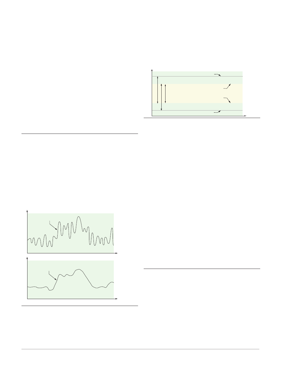
Set Point Low Limit and High Limit
The controller constrains the set point to a value be-
tween a set point low limit and a set point high limit.
Set the set point limits with Low Set Point [`L;SP]
and High Set Point [`h;SP] (Setup Page, Loop Menu).
There are two sets of set point low and high lim-
its: one for a closed-loop set point, another for an
open-loop set point.
Set Point Range (must be between Range High and Range Low)
Low Limit of selected functional range
High Limit of selected functional range
Gas Pressure
Range Low and Range High
Range High Range (between High Limit of Sensor and Range Low)
Range Low Range (between Low Limit of Sensor and Range High)
Set Point Low
Set Point High
Scale High and Scale Low
When an analog input is selected as process voltage
or process current input, you must choose the value
of voltage or current to be the low and high ends. For
example, when using a 4 to 20 mA input, the scale
low value would be 4.00 mA and the scale high value
would be 20.00 mA. Commonly used scale ranges are:
0 to 20 mA, 4 to 20 mA, 0 to 5V, 1 to 5V and 0 to 10V.
You can create a scale range representing other
units for special applications. You can reverse scales
from high values to low values for analog input sig-
nals that have a reversed action. For example, if 50
psi causes a 4 mA signal and 10 psi causes a 20 mA
signal.
Scale low and high low values do not have to match
the bounds of the measurement range. These along
with range low and high provide for process scaling
and can include values not measureable by the con-
troller. Regardless of scaling values, the measured val-
ue will be constrained by the electrical measurements
of the hardware.
Select the low and high values with Scale Low
[`S;Lo]
and Scale High [`S;hi]. Select the displayed
range with Range Low [`r;Lo] and Range High
[`r;hi]
(Setup Page, Analog Input Menu).
Range High and Range Low
With a process input, you must choose a value to rep-
resent the low and high ends of the current or voltage
range. Choosing these values allows the controller’s
display to be scaled into the actual working units of
measurement. For example, the analog input from a
humidity transmitter could represent 0 to 100 per-
cent relative humidity as a process signal of 4 to 20
mA. Low scale would be set to 0 to represent 4 mA
and high scale set to 100 to represent 20 mA. The in-
dication on the display would then represent percent
humidity and range from 0 to 100 percent with an
input of 4 to 20 mA.