Saving and restoring user settings, Inputs, Saving and restoring user settings inputs – Watlow EZ-ZONE RMH User Manual
Page 104: Calibration offset, Calibration
Watlow EZ-ZONE
®
RMH Module
•
101
•
Chapter 6 Features
Saving and Restoring User Settings
Recording setup and operations parameter settings
for future reference is very important. If you uninten-
tionally change these, you will need to program the
correct settings back into the controller to return the
equipment to operational condition.
After you program the controller and verify prop-
er operation, use User Save Set [USr;S] (Setup Page,
Global Menu) to save the settings into either of two
files in a special section of memory. If the settings
in the controller are altered and you want to return
the controller to the saved values, use User Restore
Set [USr;r] (Setup Page, Global Menu) to recall one
of the saved settings. A digital input or the Function
Key can also be configured to restore parameters.
Note:
Starting with firmware release 6, there is only one
user set.
Note:
Only perform the above procedure when you are
sure that all the correct settings are programmed
into the controller. Saving the settings overwrites
any previously saved collection of settings.
Be sure to document all the controller settings.
Note:
When restoring factory defaults, I/O assemblies for
Modbus, DeviceNet, Profibus and Ethernet along
with the zone address will be overwritten when re-
storing factory defaults.
Inputs
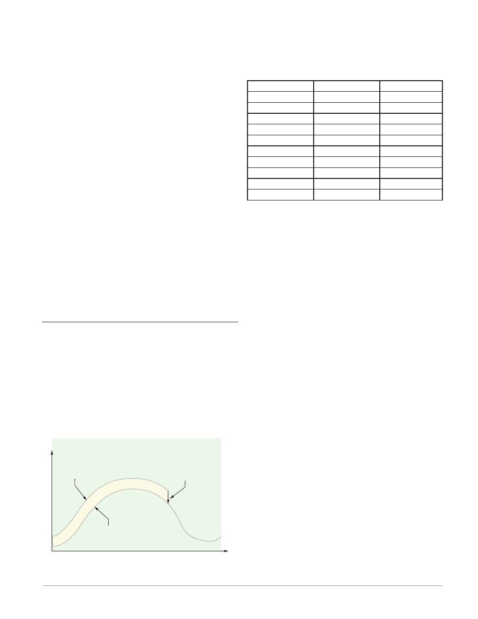
Calibration Offset
Calibration offset allows a device to compensate for
an inaccurate sensor, lead resistance or other factors
that affect the input value. A positive offset increases
the input value, and a negative offset decreases the
input value.
The input offset value can be viewed or changed
with Calibration Offset [`i;CA] (Operations Page,
Analog Input Menu).
Time
Temperature
Temperature Reading
from Sensor
Actual Process Temperature
Negative Calibration Offset will
compensate for the difference
between the Sensor Reading and
the Actual Temperature
Calibration
To calibrate an analog input, you will need to provide
two electrical signals or resistance loads near the ex-
tremes of the range that the application is likely to
utilize. See recommended values below:
Sensor Type
Low Source
High Source
thermocouple
0.000 mV
50.000 mV
millivolts
0.000 mV
50.000 mV
volts
0.000V
10.000V
milliamps
0.000 mA
20.000 mA
100 Ω RTD
50.00 Ω
350.00 Ω
1,000 Ω RTD
500.00 Ω
3,500.00 Ω
Thermistor 5K
50.00 Ω
5000.00 Ω
Thermistor 10K
50.00 Ω
10000.00 Ω
Thermistor 20K
50.00 Ω
20000.00 Ω
Thermistor 40K
50.00 Ω
40000.00 Ω
Follow these steps for a thermocouple or pro-
cess input:
1. Apply the low source signal to the input you are
calibrating. Measure the signal to ensure it is ac-
curate.
2. Read the value of Electrical Measurement [`Mu]
(Factory Page, Calibration Menu) for that input.
3. Calculate the offset value by subtracting this val-
ue from the low source signal.
4. Set Electrical Input Offset [ELi;o] (Factory Page,
Calibration Menu) for this input to the offset val-
ue.
5. Check the Electrical Measurement to see whether
it now matches the signal. If it doesn’t match, ad-
just Electrical Offset again.
6. Apply the high source signal to the input. Mea-
sure the signal to ensure it is accurate.
7. Read the value of Electrical Measurement for
that input.
8. Calculate the gain value by dividing the low
source signal by this value.
9. Set Electrical Slope [ELi;S] (Factory Page, Cali-
bration Menu) for this input to the calculated
gain value.
10. Check the Electrical Measurement to see wheth-
er it now matches the signal. If it doesn’t match,
adjust Electrical Slope again.
Set Electrical Offset to 0 and Electrical Slope to 1 to
restore factory calibration.
Follow these steps for an RTD input:
1. Measure the low source resistance to ensure it
is accurate. Connect the low source resistance to
the input you are calibrating.
2. Read the value of Electrical Measurement [`Mu]
(Factory Page, Calibration Menu) for that input.
3. Calculate the offset value by subtracting this val-
ue from the low source resistance.
4. Set Electrical Input Offset [ELi;o] (Factory Page,