Watlow ez-zone, Rmh module, Chapter 1 overview – Watlow EZ-ZONE RMH User Manual
Page 17
Watlow EZ-ZONE
®
RMH Module
•
14
•
Chapter 1 Overview
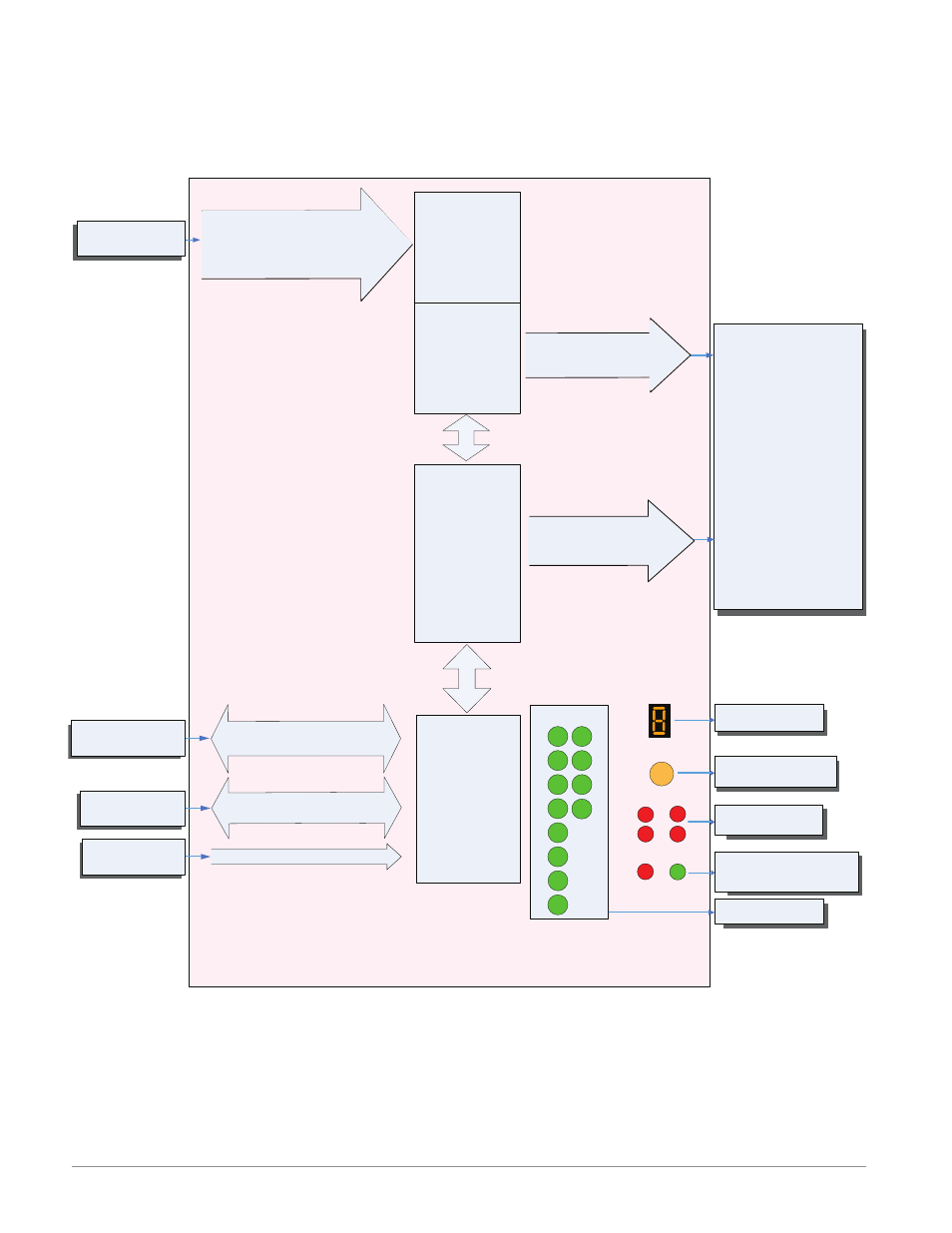
EZ-ZONE RMH Module - System Diagram
8 Control Loops - Slots A, B
3 - Process Outputs - Slot D or E
4 - SSR Outputs - Slot D or E
R M H x - [1,2] [1,2] [F,L] [F,L] - A A A A
Indicates Zone
Address
Push to select Zone
Address and Protocol
None, Thermocouple, 2-Wire RTD (100, 1k),
Thermistor (5k, 10K, 20k, 40k), Process
(V, mV, mA) or 1K Potentiometer
Analog Input 1 through 8
PID
Controller
Slot D
Output
Function
Input
Function
Some input/output combinations not possible, see ordering matrix
Zone and Status
LED
Zone Selection
Output Status
LEDs
2
3
4
5
6
1
10
9
7
8
Button
D
E
B
A
S
M
EIA - 485 Communications
Standard Bus
(optional Modbus RTU)
Inter-module Bus
Card Status
Slots A, B, D, E
Indicates I/O
Status
RUI,
PC, PLC or HMI
Other RM Modules
Power Supply
Modbus RTU
Address 1 - 16
Standard Bus
Zone 1 - 16
Supervisory &
Power Board
Slot C
20.4 to 30.8 Vac or Vdc
3 - Universal/
Retransmit
or
4 - 2A SSR
Outputs
Slot E
Indicates communications
activity (Modbus or Stand-
ard Bus)
Off
Analog Input
Current*
Alarm*
Cool Power
Heat Power
Power*
Compare*
Counter*
Digital I/O*
Profile Event Output A-H*
Function Key*
Linearization
Logic
Math
Process Value
Set Point Closed*
Set Point Open*
Special Output Function 1-4
Timer*
Variable
Slot A, B
Process, 2A Solid-State
Relay Form A
Output 1, 2, 3, 4
Input Sensor
Output 7, 8, 9, 10
11
12
3 - Universal/
Retransmit
or
4 - 2A SSR
Outputs
Process, 2A Solid-State
Relay Form A
*
*
The functions listed to the right
with purple text apply to the
Process output only, where
the orange text applies to the
SSR output only. All others
apply to both output types.