Control methods, Output configuration, Auto (closed loop) and manual (open loop) control – Watlow EZ-ZONE RMH User Manual
Page 107: On-off control
Watlow EZ-ZONE
®
RMH Module
•
104
•
Chapter 6 Features
Retransmit
Retransmit Source
Output Scale
Range High
Range Low
Scale High
Scale Low
Control Methods
Output Configuration
Each controller output can be configured as a heat
output, a cool output, an alarm output or deactivat-
ed. No dependency limitations have been placed on
the available combinations. The outputs can be con-
figured in any combination. For instance, all three
could be set to cool.
Heat and cool outputs use the set point and Oper-
ations parameters to determine the output value. All
heat and cool outputs use the same set point value.
Heat and cool each have their own set of control pa-
rameters. All heat outputs use the same set of heat
control parameters and all cool outputs use the same
set of cool output parameters.
Each alarm output has its own set of configura-
tion parameters and set points, allowing independent
operation.
Auto (closed loop) and Manual (open loop) Control
The controller has two basic modes of operation, auto
mode and manual mode. Auto mode allows the con-
troller to decide whether to perform closed-loop con-
trol or to follow the settings of Input Error Failure
[FAiL]
(Setup Page, Loop Menu). The manual mode
only allows open-loop control. The EZ-ZONE
®
RMH
controller is normally used in the auto mode. The
manual mode is usually only used for specialty appli-
cations or for troubleshooting.
Manual mode is open-loop control that allows the
user to directly set the power level to the controller’s
output load. No adjustments of the output power level
occur based on temperature or set point in this mode.
In auto mode, the controller monitors the input to
determine if closed-loop control is possible. The con-
troller checks to make certain a functioning sensor is
providing a valid input signal. If a valid input signal
is present, the controller will perform closed-loop con-
trol. Closed-loop control uses a process sensor to de-
termine the difference between the process value and
the set point. Then the controller applies power to a
control output load to reduce that difference.
If a valid input signal is not present, the control-
ler will indicate an input error message in the upper
display and [Attn] in the lower display and respond
to the failure according to the setting of Input Error
Failure [FAiL]. You can configure the controller to
perform a “bumpless” transfer [bPLS], switch power
to output a preset fixed level [MAn], or turn the out-
put power off.
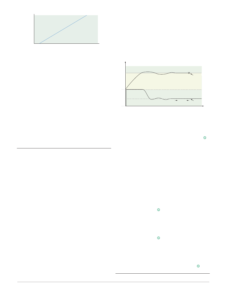
Bumpless transfer will allow the controller to
transfer to the manual mode using the last power
value calculated in the auto mode if the process had
stabilized at a ±5 percent output power level for the
time interval of Time Integral (Operations Page,
Loop) prior to sensor failure, and that power level is
less than 75 percent.
Time
Temperature
Bumpless Transfer
40%
Sensor
Break
2 minutes
Locks in
Output
Power
0%
Set Point
Actual Temperature
Output Power
Power
100%
Input Error Latching [`i;Er] (Setup Page, Ana-
log Input Menu) determines the controller’s response
once a valid input signal returns to the controller.
If latching is on, then the controller will continue
to indicate an input error until the error is cleared.
To clear a latched alarm, press the Advance Key
‰
then the Up Key ¿.
If latching is off, the controller will automatically
clear the input error and return to reading the tem-
perature. If the controller was in the auto mode when
the input error occurred, it will resume closed-loop
control. If the controller was in manual mode when
the error occurred, the controller will remain in
open-loop control.
The Manual Control Indicator Light % is on when
the controller is operating in manual mode.
You can easily switch between modes if the Con-
trol Mode [`C;M] parameter is selected to appear in
the Home Page.
To transfer to manual mode from auto mode,
press the Advance Key
‰
until [`C;M] appears in
the lower display. The upper display will display
[AUto]
for auto mode. Use the Up ¿ or Down ¯ keys
to select [Man]. The manual set point value will be
recalled from the last manual operation.
To transfer to auto mode from manual mode,
press the Advance Key
‰
until [`C;M] appears in
the lower display. The upper display will display
[MAn]
for manual mode. Use the Up ¿ or Down ¯
keys to select [AUto]. The automatic set point value
will be recalled from the last automatic operation.
Changes take effect after three seconds or imme-
diately upon pressing either the Advance Key
‰
or
the Infinity Key ˆ.
On-Off Control