Watlow ez-zone, Rmh module, Chapter 1 overview – Watlow EZ-ZONE RMH User Manual
Page 14
Watlow EZ-ZONE
®
RMH Module
•
11
•
Chapter 1 Overview
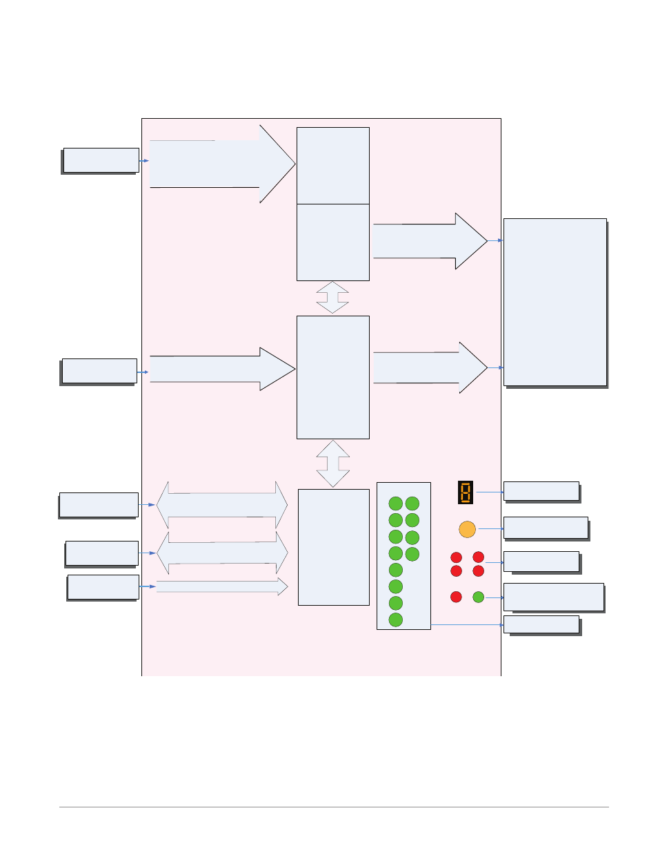
EZ-ZONE RMH Module - System Diagram
8 Control Loops - Slots A, B
4 - Form A Mechanical Relays - Slot D
6 - Digital I/O - Slot E
R M H x - [1,2] [1,2] J C - A A A A
Indicates Zone
Address
Push to select Zone
Address and Protocol
None, Thermocouple, 2-Wire RTD (100, 1k),
Thermistor (5k, 10K, 20k, 40k), Process
(V, mV, mA) or 1K Potentiometer
Analog Input 1 through 8
PID
Controller
Slot D
Output
Function
Input
Function
Some input/output combinations not possible, see ordering matrix
Zone and Status
LED
Zone Selection
Output Status
LEDs
2
3
4
5
6
1
10
9
7
8
Button
D
E
B
A
S
M
EIA - 485 Communications
Standard Bus
(optional Modbus RTU)
Inter-module Bus
Card Status
Slots A, B, D, E
Indicates I/O
Status
RUI,
PC, PLC or HMI
Other RM Modules
Power Supply
Modbus RTU
Address 1 - 16
Standard Bus
Zone 1 - 16
Supervisory &
Power Board
Slot C
20.4 to 30.8 Vac or Vdc
6 - Digital
Inputs / Outputs
any combination
Slot E
Indicates communications
activity (Modbus or Stand-
ard Bus)
Analog Input
Alarm
Cool Power
Heat Power
Compare
Counter
Digital I/O
Profile Event Output A-H
Function Key
Linearization
Logic
Math
Process Value
Special Output Function 1-4
Timer
Variable
Off
Slot A, B
4 - Mechanical
Relay Outputs
Form A
switched dc/open collector
Output 7, 8, 9, 10, 11 or 12
Digital Input 7, 8, 9, 10, 11 or 12
Switch contact or volts dc
Input Sensor
Output 1, 2, 3, 4
5A Mechanical Relay Form A
11
12
Input Device