Chapter 10: appendix, Modbus - programmable memory blocks – Watlow EZ-ZONE RMH User Manual
Page 146
Watlow EZ-ZONE
®
RMH Module
•
143
•
Appendix
7
Chapter 10: Appendix
Modbus - Programmable Memory Blocks
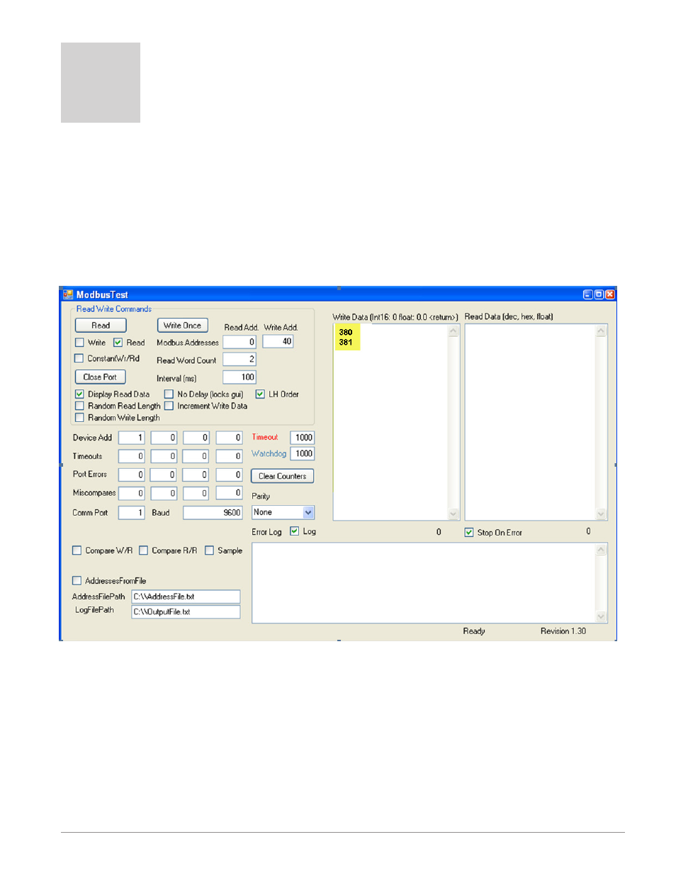
The Modbus assembly contains 40 pointers to the parameters of your choosing starting at Modbus register
40 (shown on the following page). The pointers are 32-bits long so are stored in two sequential registers. As
an example, if we want to move an alias to the analog input of the RMH (register 380) into register 40, we
perform a multiple write command (0x10 function) of 380 into register 40 and 381 into register 41 as a single
multi-write command.
Once the parameters of choice have been defined and written to the pointer registers, the working registers
200 to 279 then represent those parameters. Therefore, as in the example above, if 380 is in register 40, 381
in register 41, register 200 & 201 contains the 32-bit floating point result for analog input 1.
The screen shot above was taken from a program that can be found on the Watlow Support Tools DVD
(shipped with the product) as well as on the Watlow website. On the DVD, it can be found under "Utility
Tools" and is identified as "Modbus RTU Diagnostic Program for EZ-ZONE PM, RM and ST". A similar pro-
gram can be found here as well for a connection utilizing Ethernet TCP.
If it is easier to go to the web to acquire this software click on the link below and type "modbus" in the
search field where both versions can be found with the same name.
http://www.watlow.com/literature/soft-
ware.cfm