3 mechatrolink interface – IAI America PCON-CFA User Manual
Page 76
3. SCON-CA/CF
A
68
3.3 MECHATROLINK
Interface
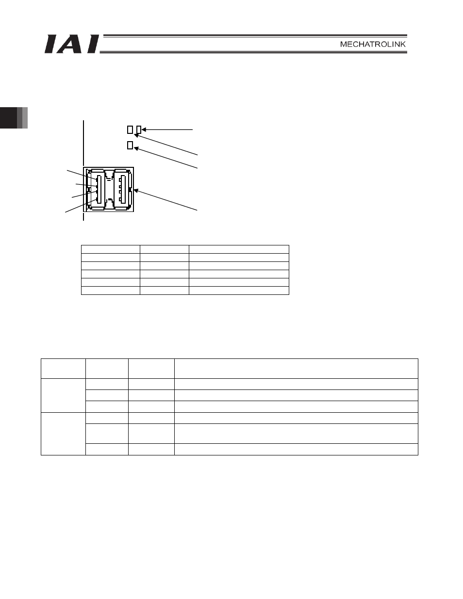
3.3.1 Name of Each Part
The name of each part relating to MECHATROLINK is shown.
MECHATROLINK communication connector (2 systems)
3.3.2 Monitor LED Indications
The operation condition of the communication board, as well as the network condition, can be checked using the
two LEDs provided on the front side of the board.
LED Color
Indicator
condition
Description
Green Lit
CONNECT
received
(Connected to the master)
Red
Lit
Communication error detected
STATUS 1
Unlit
The board is not connected to the master unit.
Green
Lit
The board is operating properly.
Red Lit
A communication hardware error was detected when the board was not
yet ready.
STATUS 0
Unlit
The board is not yet ready or the power is not supplied.
Pin No.
Signal name
Description
1 NC
Not
used
2
/DATA
– side signal
3
DATA
+ side signal
4 SH
Not
used
Connector shell
Shield
Shielded wire to be connected
NC
/DATA
DATA
SH
MECHATROLINK communication connector
PCB side: DUSB-ARB82-T11A-FA (DDK)
SV/ALM Status indicator LEDs
֥Status LEDs
Status 1
Status 0