IAI America PCON-CFA User Manual
Page 165
4. SCON-CA
157
4.6.7 Half Direct Mode 2 (Cannot be used in the 17-byte mode)
In this mode, the actuator is operated by means of force control (push-motion operation based on feedback of
load cell values) and also by specifying the target position, positioning band, speed, acceleration/deceleration
and push current directly as numerical values. Set each value in the applicable I/O area. To use the zone function,
set the necessary values in parameter Nos. 1, 2, 23 and 24.
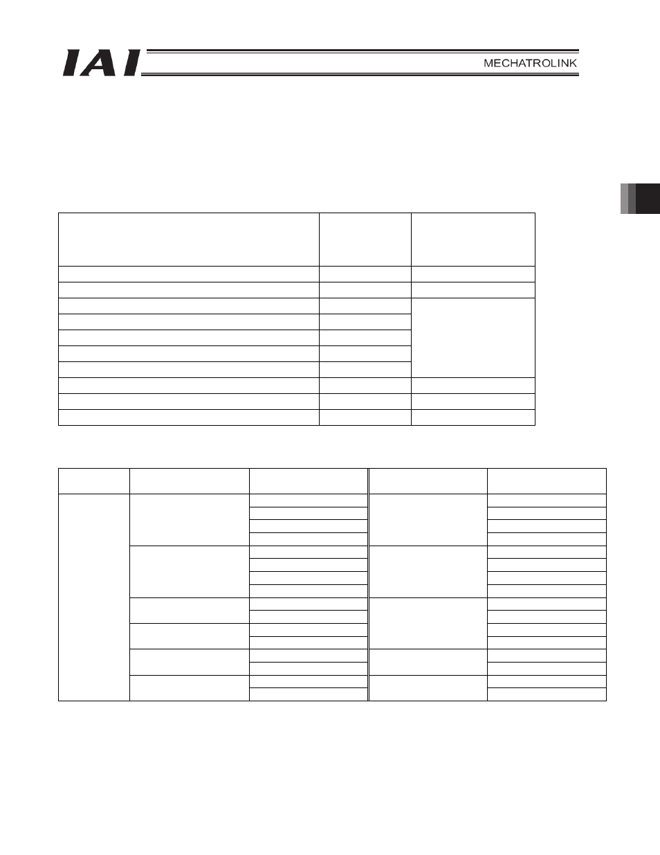
The key functions that are available on Actuators controllable in this mode are shown in the table below.
Actuator function
{: Direct control
U: Indirect
control
x: Invalid
Remarks
Home return operation
{
Positioning operation
{
Speed & acceleration/deceleration setting
{
Pitch feed (inching)
{
Push-motion operation
{
Speed change during movement
{
Operation at different acceleration and deceleration
x
Pause
{
Zone signal output
U
Parameters must be set.
PIO pattern selection
x
(1) PLC address configuration (When the DATA_RWA command is in use)
Parameter
No. 84
SCON-CA input
register
PLC output address
[
Bytes]
SCON-CA output
register
PLC input address
[
Bytes]
5 (Lower byte)
5 (Lower byte)
6 (Upper byte)
6 (Upper byte)
7 (Lower byte)
7 (Lower byte)
Target position
8 (Upper byte)
Current position
8 (Upper byte)
9 (Lower byte)
9 (Lower byte)
10 (Upper byte)
10 (Upper byte)
11 (Lower byte)
11 (Lower byte)
Positioning band
12 (Upper byte)
Force feedback data
12 (Upper byte)
13 (Lower byte)
13 (Lower byte)
Speed
14 (Upper byte)
14 (Upper byte)
15 (Lower byte)
15 (Lower byte)
Acceleration/
deceleration
16 (Upper byte)
Current speed
16 (Upper byte)
17 (Lower byte)
17 (Lower byte)
Push-current limiting
value
18 (Upper byte)
Alarm code
18 (Upper byte)
19 (Lower byte)
19 (Lower byte)
6
Control signal
20 (Upper byte)
Status signal
20 (Upper byte)
(Note) Pay attention to use of duplicate node addresses.