6 communication with the master station – IAI America PCON-CFA User Manual
Page 26
2. ACON-C/CG,
PCON-C/CG
18
2.6
Communication with the Master Station
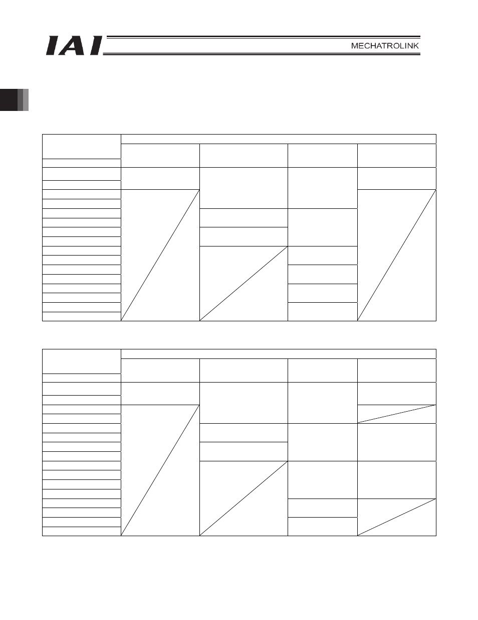
2.6.1 Operation Modes and Handling of PLC Addresses
The address assignments under each operation mode are shown below.
x PLC
output
o ACON/PCON input
ACON/PCON DI and input data resister
PLC output address
(When the DATA_RWA
command is in use)
Bytes
Remote I/O mode
Position/simple direct
mode
Half direct mode
Remote I/O mode 2
5
6
Port number 0 to 15
Port number 0 to 15
7
8
Target position
Target position
9
10
Specified position number
11
12
Control signal
Positioning band
13
14
Speed
15
16
Acceleration/
deceleration
17
18
Push-current limiting
value
19
20
Control signal
(Note) Pay attention to use of duplicate node addresses.
x ACON/PCON
output
o PLC input
ACON/PCON DO and output data resister
PLC input address
(When the DATA_RWA
command is in use)
Bytes
Remote I/O mode
Position/simple direct
mode
Half direct mode
Remote I/O mode 2
5
6
Port number 0 to 15
Port number 0 to 15
7
8
Current position
Current position
9
10
Completed position
number (simple alarm ID)
11
12
Status signal
Command current
Current position
13
14
15
16
Current speed
Command current
17
18
Alarm code
19
20
Status signal
(Note) Pay attention to use of duplicate node addresses.