IAI America PCON-CFA User Manual
Page 222
5. Flow and Commands of Basic MECHA
TROLINK Communication
214
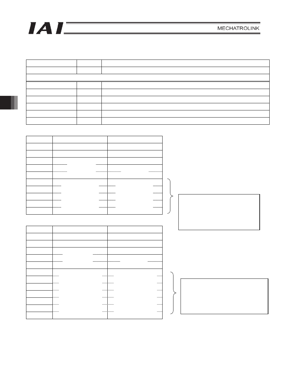
[6] DATA_RWA command
Command Code
Name
DATA_RWA
50H
Data read/write command
Updates (Transmits) the I/O data.
Field (Signal) name
Value
Description
OPTION[2 to 0]
Not used: Specify 0
OUTPUT[11 to 0]
[In the 17-byte mode] Updated data from the master unit to the slave
OUTPUT[26 to 0]
[In the 32-byte mode] Updated data from the master unit to the slave
INPUT[11 to 0]
[In the 17-byte mode] Updated data from the slave to the master unit
INPUT[26 to 0]
[In the 32-byte mode] Updated data from the slave to the master unit
z 17-byte mode format
Byte Command
Response
0 CDRW(03H)
ACK(01H)
1 DATA_RWA(50H)
DATA_RWA(50H)
2
ALARM
3
4
5
6
:
15
16
z 32-byte mode format
Byte Command
Response
0 CDRW(03H)
ACK(01H)
1 DATA_RWA(50H)
DATA_RWA(50H)
2
ALARM
3
4
5
6
7
:
29
30
31
STATUS
OPTION
OUTPUT[0]
OUTPUT[1]
:
OUTPUT[10]
OUTPUT[11]
INPUT[0]
INPUT[1]
:
INPUT[10]
INPUT[11]
STATUS
OPTION
OUTPUT[0]
OUTPUT[1]
OUTPUT[2]
:
OUTPUT[24]
OUTPUT[25]
OUTPUT[26]
INPUT[0]
INPUT[1]
INPUT[2]
:
INPUT[24]
INPUT[25]
INPUT[26]
Each data register in Section 2.6.1, 3.6.1 and
4.6.1 corresponds to each mode.
Example) In the position/simple direct mode
y The target positions correspond to bytes 5
through 8 (OUTPUT 0 through 3).
y The current position corresponds to bytes 5
through 8 (INPUT 0 through 3).
Each data register in Section 2.6.1, 3.6.1 and
4.6.1 corresponds to each mode.
Example) In the half direct mode
y The positioning band corresponds to bytes 9
through 12 (OUTPUT 4 through 7).
y The command electricity corresponds to bytes
9 through 12 (INPUT 4 through 7).