IAI America PCON-CFA User Manual
Page 46
2. ACON-C/CG,
PCON-C/CG
38
(1) PLC address configuration
Parameter
No. 84
ACON/PCON DI and
input register
PLC output address
[
Bytes]
ACON/PCON DO and
output register
PLC input address
[
Bytes]
5 (Lower byte)
5 (Lower byte)
Port number 0 to 15
6 (Upper byte)
Port number 0 to 15
6 (Upper byte)
7
8
9 (Lower byte)
10 (Upper byte)
11 (Lower byte)
Current position
12 (Upper byte)
13 (Lower byte)
14 (Upper byte)
15 (Lower byte)
4
7 to 16
Command current
16 (Upper byte)
(Note) Pay attention to use of duplicate node addresses.
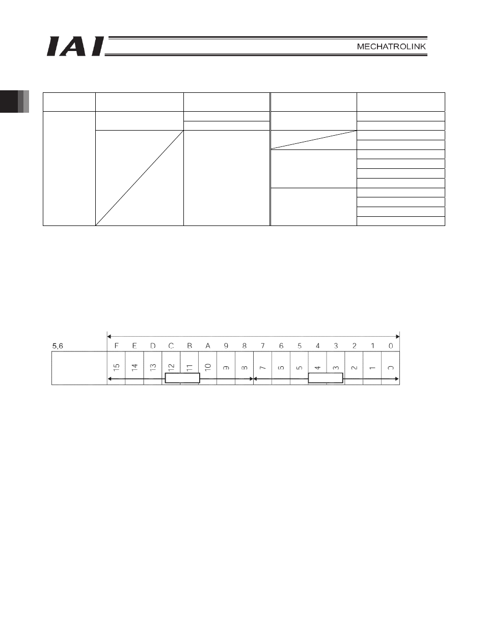
(2) I/O signal assignments for each axis
An I/O signal of each axis consists of 12 bytes of I/O addresses.
z Addresses controlled by port numbers are controlled by bit ON/OFF signals.
z The current position is 4 bytes (32-bit) binary data (unit: 0.01 mm).
z The command current is 4 bytes (32-bit) binary data (unit: 1 mA).
PLC output address
Bytes
2 bytes = 16 bits
Controller
input port
number
Lower byte
Upper byte