IAI America PCON-CFA User Manual
Page 28
2. ACON-C/CG,
PCON-C/CG
20
(1) PLC address configuration (When the DATA_RWA command is in use)
Parameter
No. 84
ACON/PCON DI
(port number)
PLC output address
[
Bytes]
ACON/PCON DO
(port number)
PLC input address
[
Bytes]
5 (Lower byte)
5 (Lower byte)
0
0 to 15
6 (Upper byte)
0 to 15
6 (Upper byte)
(Note) Pay attention to use of duplicate node addresses.
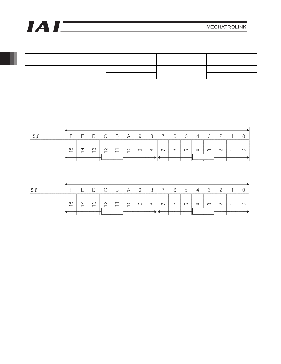
(2) I/O signal assignments for each axis
An I/O signal of each axis consists of 1 word (2 bytes) of I/O addresses.
z I/O addresses are controlled by bit ON/OFF signals from the PLC.
PLC output address
PLC input address
Bytes
2 bytes = 16 bits
2 bytes = 16 bits
Controller
input port
number
Controller
output port
number
Lower byte
Upper byte
Lower byte
Upper byte