IAI America PCON-CFA User Manual
Page 143
4. SCON-CA
135
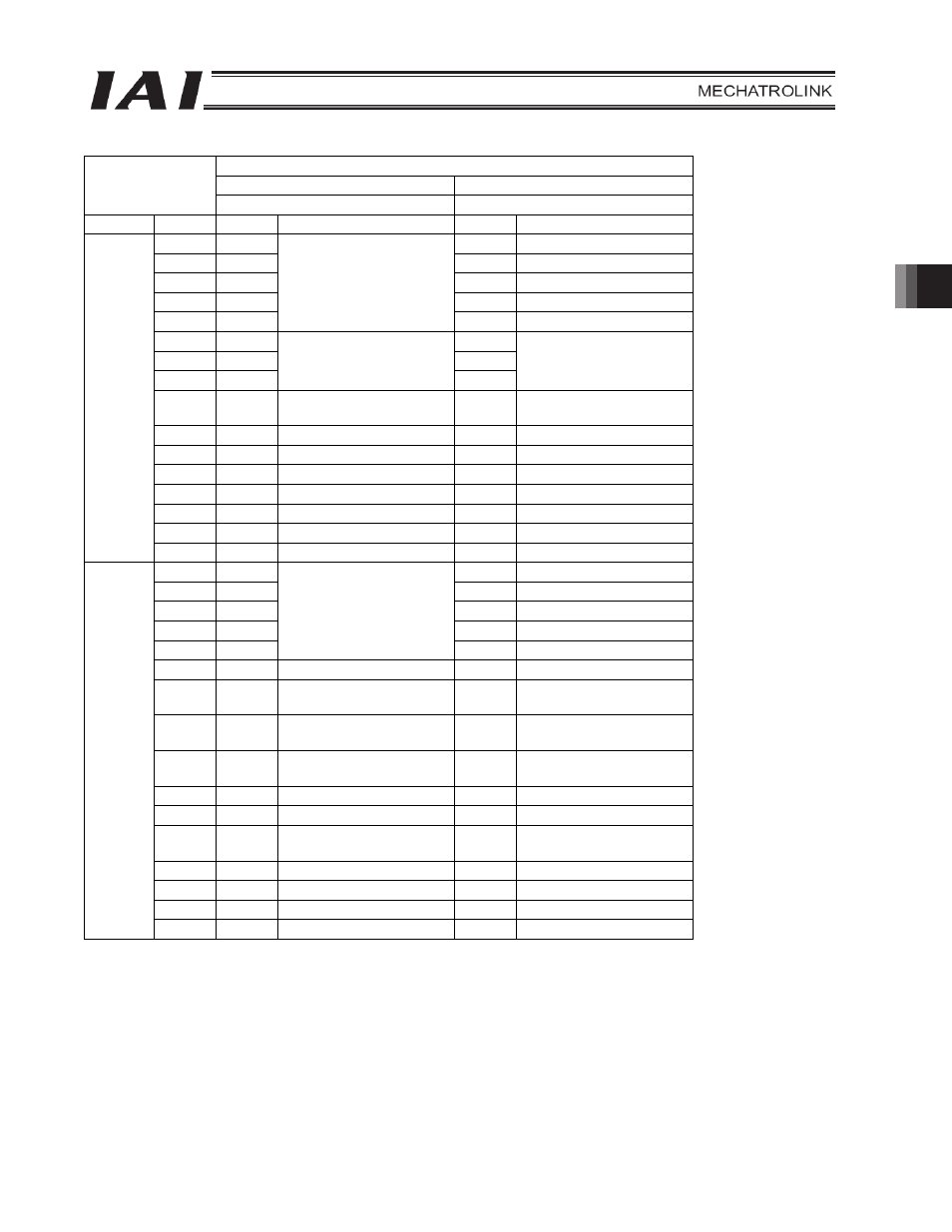
Setting of parameter No. 25
Force control mode 1
Force control mode 2
6 7
Category Port
No. Symbol
Signal
name Symbol
Signal
name
0 PC1
ST0
Start
position
0
1 PC2
ST1
Start
position
1
2 PC4
ST2
Start
position
2
3 PC8
ST3
Start
position
3
4 PC16
Command position number
ST4 Start
position
4
5 -
-
6 -
-
7 -
Cannot be used.
-
Cannot be used.
8 CLBR
Load cell calibration
command
CLBR -
Load cell calibration
command
9
BKRL
Forced brake release
BKRL
Forced brake release
10
RMOD
Operation mode
RMOD
Operation mode
11
HOME Home
return HOME
Home
return
12
*STP Pause *STP Pause
13
CSTR
Positioning start
-
Cannot be used.
14 RES
Reset
RES
Reset
PLC
output
o
SCON-CA
input
15
SON
Servo ON command
SON
Servo ON command
0 PM1
PE0
Completed position number 0
1 PM2
PE1
Completed position number 1
2 PM4
PE2
Completed position number 2
3 PM8
PE3
Completed position number 3
4 PM16
Completed position
number
PE4
Completed position number 4
5
TRQS
Torque level status
TRQS
Torque level status
6 LOAD
Load output judgment
status
LOAD
Load output judgment
status
7 CEND
Load cell calibration
complete
CEND
Load cell calibration
complete
8
PZONE/
ZONE1
Position zone/
Zone 1
PZONE/
ZONE1
Position zone/
Zone 1
9
RMDS
Operation mode
RMDS
Operation mode
10
HEND
Home return complete
HEND
Home return complete
11 PEND
Positioning complete
signal
PEND
Positioning complete
signal
12
SV Operation
ready SV Operation
ready
13
*EMGS Emergency
stop *EMGS
Emergency
stop
14
*ALM Alarm *ALM
Alarm
SCON-CA
output
o
PLC input
15
*BALM
Battery alarm
*BALM
Battery alarm
* Indicates a signal that is normally ON.
The signals denoted by “Cannot be used” are not controlled. (ON/OFF statuses of these signals are
indeterminable.)