IAI America PCON-CFA User Manual
Page 39
2. ACON-C/CG,
PCON-C/CG
31
(2) I/O signal assignments for each axis
An I/O signal of each axis consists of 16 bytes of I/O addresses.
z Control signals and status signals are bit ON/OFF signals.
z The target position and current position are both 4 bytes (32-bit) binary data. Although values from -999999 to
+999999 (unit: 0.01 mm) can be handled by the PLC, set position data within the software stroke range (0 up
to the effective stroke length) of the applicable actuator.
z Set a desired positioning band. The positioning band is 4 bytes (32-bit) binary data and values from 1 to
+999999 (unit: 0.01 mm) can be handled by the PLC.
z The speed is 2 bytes (16-bit) binary data. Although values from 0 to +65535 (unit: 1.0 mm/sec) can be handled
by the PLC, set a value not exceeding the maximum speed of the applicable actuator.
z The acceleration/deceleration is 2 bytes (16-bit) binary data. Although values from 1 to 300 (unit: 0.01 G) can
be handled by the PLC, set a value not exceeding the maximum acceleration and maximum deceleration of
the applicable actuator.
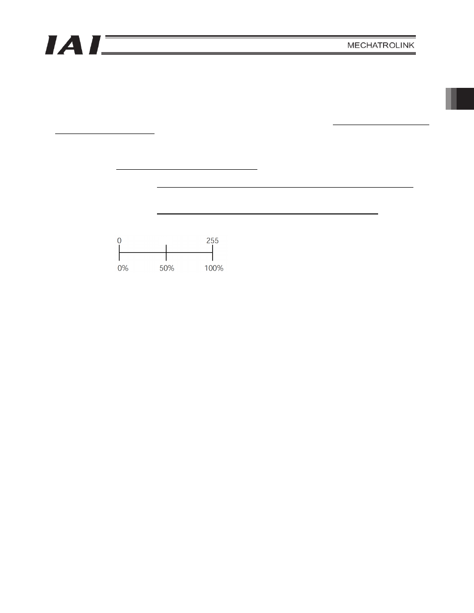
z The push-current limiting value is 2 bytes (16-bit) binary data. Although values from 0 (0%) to 255 (100%) can
be handled by the PLC, set a value within the specifiable range of push-current limiting values of the
applicable actuator (refer to the catalog or operation manual for the actuator).
z The command current is 4 bytes (32-bit) binary data (unit: 1 mA).
z The current position is 4 bytes (32-bit) binary data (unit: 0.01 mm/sec).
z The alarm code is 2 bytes (16-bit) binary data.
Set value
Push-current
limiting value
127