IAI America PCON-CFA User Manual
Page 33
2. ACON-C/CG,
PCON-C/CG
25
2.6.3 Position/Simple Direct Mode
In this mode, the actuator is operated by specifying position numbers. You can select whether to set the target
position directly as a value or use a value registered in the position data table, by switching a control signal
(PMOD signal).
For all data other than the target position, such as speed, acceleration/deceleration and positioning band, values
in the controller’s position table are used. Set desired position data by referring to the operation manual for the
controller.
Up to 768 position data points can be set.
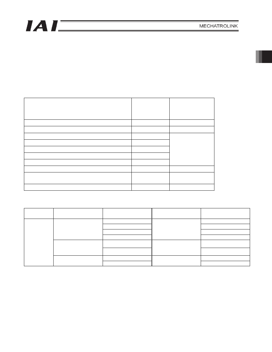
The key functions that are available on ROBO Cylinders controllable in this mode are shown in the table below.
ROBO Cylinder function
{: Direct control
U: Indirect
control
x: Invalid
Remarks
Home return operation
{
Positioning operation
{
Speed & acceleration/deceleration setting
U
Pitch feed (inching)
U
Push-motion operation
U
Speed change during movement
U
Operation at different acceleration and deceleration
U
Position data must
be set
Pause
{
Zone signal output
U
Zones are set using
parameters.
PIO pattern selection
x
(1) PLC address configuration (When the DATA_RWA command is in use)
Parameter
No. 84
ACON/PCON input
register
PLC output address
[
Bytes]
ACON/PCON output
register
PLC input address
[
Bytes]
5 (Lower byte)
5 (Lower byte)
6 (Upper byte)
6 (Upper byte)
7 (Lower byte)
7 (Lower byte)
Target position
8 (Upper byte)
Current position
8 (Upper byte)
9 (Lower byte)
9 (Lower byte)
Specified position
number
10 (Upper byte)
Completed position
number
(simple alarm code)
10 (Upper byte)
11 (Lower byte)
11 (Lower byte)
1
Control signal
12 (Upper byte)
Status signal
12 (Upper byte)
(Note) Pay attention to use of duplicate node addresses.