IAI America IX-NSN6016H User Manual
Page 58
50
7. Specifications
Item
Specifications
Surrounding air temperature/humidity
Temperature: 0 to 40
°
C, humidity: 20 to 85%RH or
less (non-condensing)
Operating
environment
s
s
e
l
r
o
0
0
0
,
1
m
e
d
u
t
i
t
l
A
B
d
e
s
i
o
N
73
Robot weight
kg
29.5
Power supply
230 V 50/60 Hz 8 A
Allowable supply voltage
fluctuation
%
±
10
Overvoltage category (IEC60664-1)
Category III
Controller
3
e
e
r
g
e
d
n
o
i
t
u
ll
o
P
)
1
-
4
6
6
0
6
C
E
I
(
e
e
r
g
e
d
n
o
i
t
u
ll
o
P
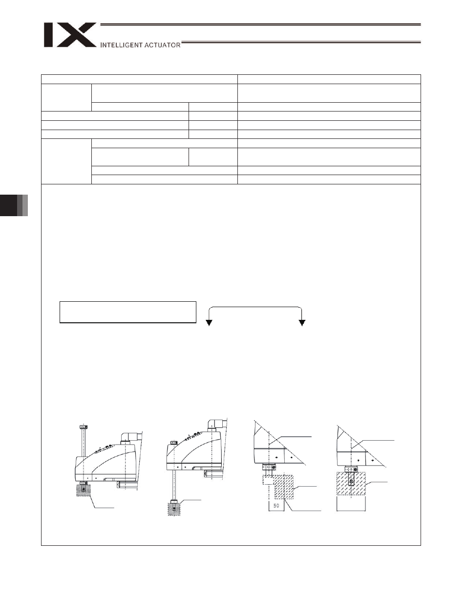
Note 1) To move the robot horizontally at high speed, perform teaching so that the vertical axis stays as close to the top
position as possible. (Fig. 1)
To operate the robot with its vertical axis at the bottom position, the speed and acceleration must be reduced as
appropriate. (Fig. 2)
Note 2) Assuming PTP instruction operation. The maximum composite speed is not the maximum speed of CP operation.
Note 3) Positioning precision when the robot is operated repeatedly to one specified position from the same starting
position at the same speed and acceleration/deceleration using the same arm (at a constant surrounding air
temperature of 20
°
C). Take note that this is not the absolute positioning precision.
Also note that the positioning repeatability may deviate from the specified value if the arm is changed, positioning
is performed to one specified position from multiple positions, or any of the operating conditions such as operating
speed and acceleration/deceleration setting is changed.
Note 4) Measured when the robot is operated at the maximum speed, carrying a load of 2 kg.
This cycle time assumes a reciprocating operation involving a vertical travel of 25 mm and horizontal travel of 300
mm. (Rough positioning)
Note 5) The permissible moment of inertia converted to a value at the rotational center of axis 4. The offset from the
rotational center of axis 4 to the tool’s center of gravity is assumed to be 50 mm or less. (Fig. 3)
If the tool’s center of gravity is further away from the rotational center of axis 4, the speed and acceleration must be
reduced as appropriate.
Note 6) If the tool exceeds the permissible diameter, it will contact the robot inside the robot’s range of movement. (Fig. 4)
Note 7) To enable the alarm LED indicator, the user must provide a circuit that supplies 24 VDC to the LED terminal in the
user connector in response to the controller I/O output signal, etc.
Note 8) Push force when driver card parameter No. 38, “Push torque limit during positioning” is set to 70%.
Note 9) Push force when driver card parameter No. 38, “Push torque limit during positioning” is set to 20%.
Although this parameter can be set to a desired value from 15 to 70%, push force will not stabilize if the set value
is outside the range of 40 to 70%.
Reference design standards: Annex I to Machine Directives, EN292-1, EN292-2, EN1050, EN60204-1, EN775
Note: Continuous operation at the
maximum speed is not feasible.
25 mm
300 mm
Top
position
Tool
Bottom
position
Tool
Center of
rotational axis
Tool
40
Tool’s center
of gravity
Tool
Center of
rotational axis
φ 100
Fig. 1
Fig. 2
Fig. 3
Fig. 4
Brake power source for main unit
W
DC24VI10% 20W