IAI America IX-NSN6016H User Manual
Page 21
13
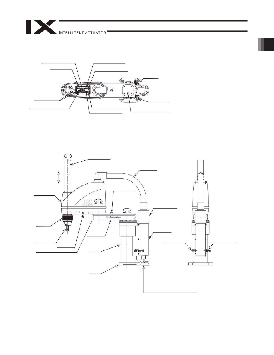
1. Name of Each Part
IX-NNW50
H/60 H/70 H/80 H
ALM (indicator)
User piping
4, black
User piping
6 red
User Connector
Top cover (arm 1)
BK SW
(Brake- release switch)
Spacer for user
part installation
User piping
6, yellow
User piping
4, white
Exhaust/intake port
Suction joint
Cover
(arm 2)
End cover (arm 1)
Axis 3
(vertical axis)
Axis 4
(rotational axis)
Mechanical stopper
for arm 1, arm 2
Mechanical
stopper for arm 1
Bellows
Wiring duct
Dust cover
Cover (base)
Arm 1
Reference
surface
Base
M cable (outside robot)
PG cable (outside robot)
U cable (outside robot)
BK power cable
Airtube (
4: 2pcs. 6: 2pcs.)
Exhaust/intake
port
Air supply port for air
purge
External diameter
6
(internal diameter
4)
Axis 2
Axis 1
Arm 2
Ball screw
spline shaft
This manual is related to the following products: