20 2. external dimensions, Ix-nnn80 h – IAI America IX-NSN6016H User Manual
Page 28
20
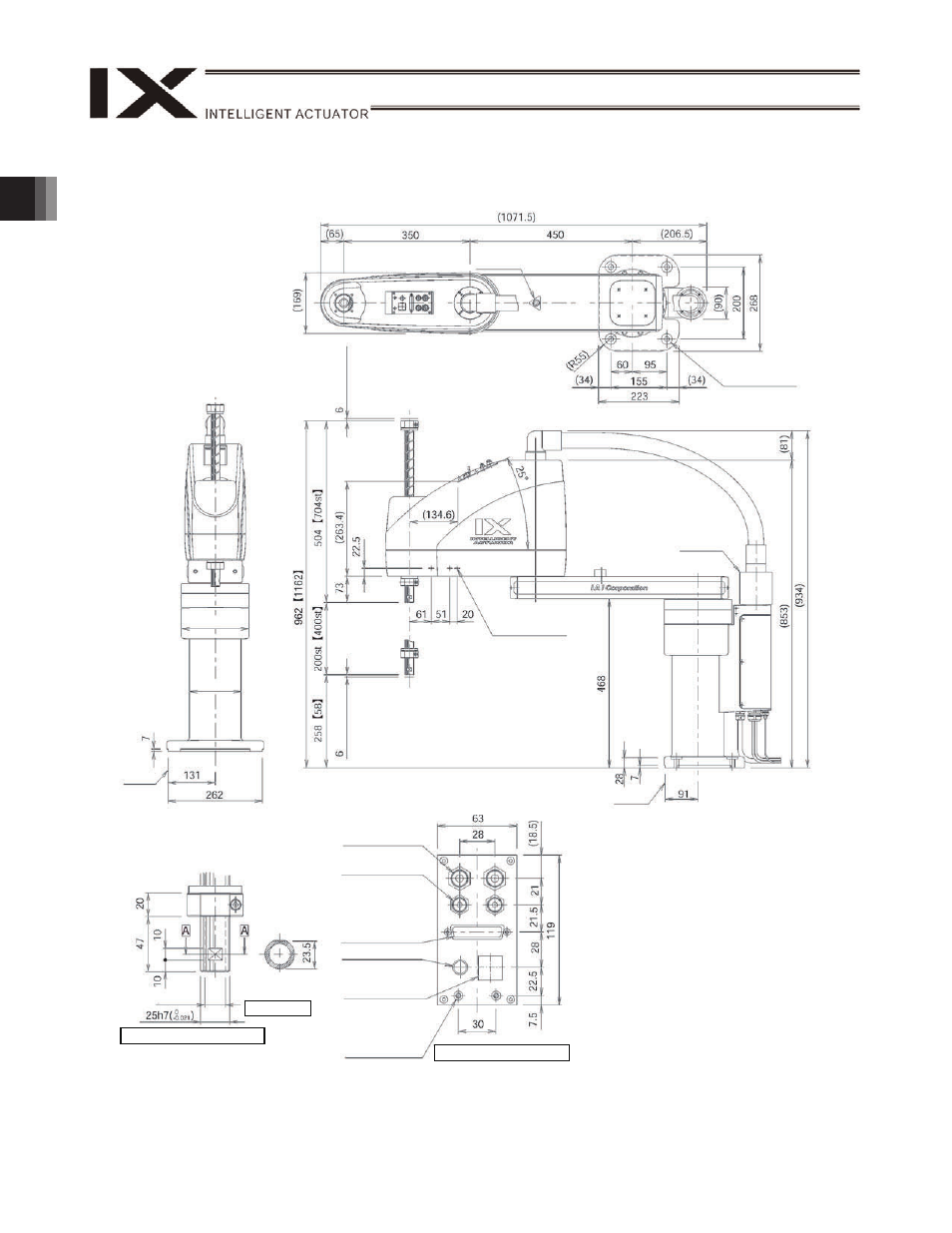
2. External Dimensions
(
188)
(
144)
Arm 2
stopper
4-14 bore
30 counterbored, depth 5
Reference
surface
2-M4, depth 8
Same on opposite
side (Note 1)
Note 1: The prepared holes denoted by “3-M4, depth
8” are through holes connecting both sides of
the arm.
Note 2: External force applied to the spacers must not
exceed 30 N in the axial direction or 2 N
m in
the rotating direction (for each spacer).
Note 3: The LED operates only when the user
provides a circuit that receives controller I/O
output signal and supplies 24 VDC to the LED
terminal in the user connector.
(M
echani
cal
end)
(M
e
chanical end)
Reference
surface
18 hollow
Quick joint for
6 air tube
User connector
(D-sub connector for
user wiring)
(25-pin, socket,
fastener size M2.6)
BK SW
(Brake-release
switch)
Spacer outer
diameter
7
Height 10, M4,
depth 5 (Note 2)
Detail view of panel (1/2)
Quick joint for
4 air tube
ALM (Note 3)
Detail view of arm end (1/2)
Section A-A
Arm 1,
arm 2
stopper
IX-NNN80
H
Red
Yellow
Black
White