Wiring diagram, 1 layout drawing, 33 4. w iring diagram – IAI America IX-NSN6016H User Manual
Page 41
33
4. W
iring Diagram
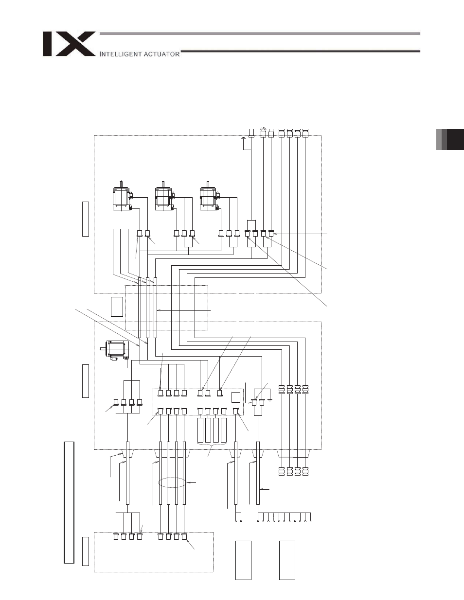
Notes
(1)
The actual la
y
out
of board conn
ectors varies from
this draw
ing.
(2)
Since the brake
po
w
er circuit is pr
ovided on the
p
rimary
side (high-voltage
side)
, a dedicated 24 V po
w
e
r suppl
y
is req
uire
d
for
this circuit.
The 24 V po
wer
supply
for I/
O circuits used on the
secondary
side (low
-voltage side) cannot be share
d.
(3)
To operate the al
arm LED, the
user must provide
a circuit
that uses
the
controller I/
O output signal.
S
e
rv
o moto
r w
ith
bra
k
e
fo
r
a
x
is
4
(R-
ax
is)
FG (to D-sub
ho
using
)
Contr
oller
In
side
ba
se
Flex
ible
cable
In
side
arm
2
Brake
pow
er
terminal
s
User
w
iring
terminal
s
Cable
fix
cap
(Capcon)
M cable (o
utside
robo
t)
D
W
G
N
o.
10
686
55*
172
159-
1
(T
y
co Electronics
AMP
)
Ser
v
o
m
ot
or
for
ax
is
1
(arm
1
)
D
W
G
N
o.
10
693
63*
PG ca
ble (inside
robo
t)
M
c
a
b
le
(in
side
ro
bo
t)
U cable (insid
e
rob
ot)
Ser
v
o
m
ot
or
for
ax
is
2
(arm
2
)
Socket
172
159-
1
(T
y
co
Electronics AMP
)
Ser
v
o
mot
or
w
ith
brake
for
ax
is
3
(Z-axis)
Socket
172
157-
1
(T
y
co
Electronics AMP
)
D-s
ub
co
nne
ct
o
r
fo
r
us
er
w
irin
g
(25
-p
in
,
soc
ke
t)
Al
ar
m
L
ED
Brake-releas
e sw
itch for ax
es 3/4
(Z/R-ax
e
s
)
Air
joint,
b
la
ck
(
4
)
Air
joint,
red
(
6
)
Air
joint,
w
hite
(
4
)
Plug
172
166-
1
(T
y
co Electronics
AMP
)
Socket
DF11-
14DS-
2C
(Hirose)
Air
joint,
red
(
6
)
Air
joint,
y
ellow
(
6)
Air
joint,
b
la
ck
(
4
)
Plug
DF11-
14DEP-
2C
(Hirose)
FG (T
o
bas
e)
Connec
tor
X
AP-
02V-
1
(J
S
T
)
PG ca
ble (ou
tside ro
bo
t)
D
W
G
N
o.
10
686
56*
BK p
o
w
e
r cable (ou
tside rob
o
t)
U cable (o
utside
rob
o
t)
Dedicate
d
b
att
eries
fo
r IX
: AB-3
D
W
G
N
o.
10
686
57*
Plug
-in
conne
cto
r con
tac
t
JK-SP2140
(JS
T)
Cont
act
cable
D13A
(DDK)
Plu
g
G
IC2
.5/4-
ST
F-7.62
(P
hoen
ix
Co
ntact)
M1
M2
M3
M4
PG
1
PG
2
PG
3
PG
4
M1
M2
M3
M4
PG
2
M2
PG
3
M3
BK
3
PG
4
M4
BK
4
LED
BK
User
Conn
ector
ALM
BK
S
W
INPG
1
INPG
2
INPG
3
INPG
4
OUT
P
G1
OUT
P
G4
BK
4
BK
3
OUT
P
G2
OUT
P
G3
SW
BAT
1
BAT
2
BAT
3
BAT
4
24
V
DC
UA
UB
+24
V
G2
4
V
U1
U2
U3
U13
U14
U15
LED
+2
4V
LED
G2
4V
FG
D
W
G
N
o.
10
686
51*
Plug
172
165-
1
(T
y
c
o Electronics
AMP
)
Socket
DF3-
2S-
2C
(Hirose)
Socket
DF3-3C-2C
(Hirose)
Boar
d
Air
joint,
w
hite
(
4
)
D
W
G
N
o.
10
693
64*
Soc
k
et
1721
61-
1
(T
y
c
o
Elec
tr
o
nic
s
A
MP)
UA
UB
Air
joint,
y
ellow
(
6)
Wiring/Piping Diagram: 500/6
00/7
00/800
Socket
DF11-
14DS-
2C
(Hirose
)
Connect
or
HI
F3BA-
10D-
2.
54
(Hir
o
s
e)
Plug
172169-1
(T
y
c
o
Elec
tr
onics
AM
P)
4.
Wiring Diagram
4.1
Layout Drawing
IX-NNN50
H/60
H/70
H/80
H
IX-NNC50
H/60
H/70
H/80
H
φ
φ
φ
φ
φ
φ
φ
φ