35 4. w iring diagram – IAI America IX-NSN6016H User Manual
Page 43
35
4. W
iring Diagram
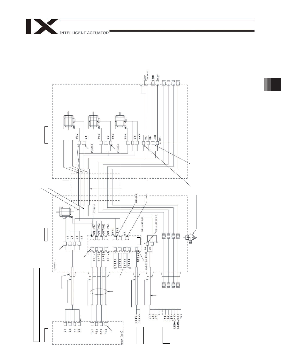
Notes
(1)
The actual la
y
out
of board conn
ectors varies from
this draw
ing.
(2)
Since the brake
po
w
er circuit is pr
ovided on the
p
rimary
side (high-voltage
side)
, a dedicated 24 V po
w
e
r suppl
y
is req
uire
d
for
this circuit.
The 24 V po
wer
supply
for I/
O circuits used on the
secondary
side (low
-voltage side) cannot be share
d.
(3)
To operate the al
arm LED, the
user must provide
a circuit
that uses
the
controller I/
O output signal.
(4)
User
w
iring termi
nals U24 and U2
5 cannot be used
.
Controller
Insi
d
e
base
Flex
ible
cable
Inside
arm
2
Brake p
o
w
e
r
term
in
als
User
w
ir
ing
term
in
als
Cable
fi
x
cap
(C
apc
on)
M
c
abl
e
(ou
ts
ide
robot)
D
W
G
No.
10686
55*
(T
y
c
o
E
le
ct
ro
n
ics
A
M
P
)
S
e
rvo
m
o
tor
fo
r
ax
is
1
(ar
m
1)
D
W
G
No.
10693
63*
PG
c
abl
e
(i
ns
ide
robot)
M
c
abl
e
(i
ns
ide
robot)
U
c
a
b
le
(ins
id
e
ro
bot)
S
e
rvo
m
o
tor
fo
r
ax
is
2
(ar
m
2)
Soc
k
et
(T
y
c
o
E
le
ct
ro
ni
cs
AM
P)
Servo
m
otor
w
ith
br
ak
e
for
ax
is
3
(Z
-
ax
is
)
Soc
k
et
(T
y
c
o
E
le
ct
ro
ni
cs
AM
P)
Serv
o
m
otor
with
brak
e
fo
r
a
xi
s
4
(R-axi
s)
FG
(t
o
D
-s
ub
ho
us
in
g)
W
a
te
rp
roof
c
onnec
tor
for
us
e
r
wiri
n
g
(24
pins)
24
p
ins
in
c
lu
de
a
s
h
ie
ld
ter
m
inal.
Alar
m
LED
Brak
e-releas
e
s
w
itc
h
for
ax
es
3/4
(Z/R-ax
es
)
Air
joi
nt,
blac
k
(
4)
Air
jo
int, r
e
d
(
6
)
Air
jo
int,
whit
e (
4)
Plu
g
(T
y
c
o
E
le
ct
ro
n
ics
A
M
P
)
Soc
k
et
DF11-14D
S-
2C
(Hiros
e)
Air
jo
int, r
e
d
(
6
)
Air
joi
nt,
y
e
llo
w
(
6)
A
ir
jo
in
t,
b
la
c
k
(
4
)
Plu
g
(H
ir
os
e)
FG
(T
o
base)
Conn
ector
PG
c
abl
e
(ou
ts
ide
robot)
D
W
G
No.
10686
56*
BK
po
wer
c
abl
e
(outs
ide
ro
bot)
U
c
a
b
le
(outs
ide
ro
bot)
Dedic
a
ted
batt
er
ies
for
IX
:
AB-3
D
W
G
No.
10686
57*
Plu
g-in
c
onn
ec
tor
c
ontac
t
JK
-S
P2140
(JS
T
)
Contact
c
a
b
le
D13A
(DD
K
)
Plu
g
G
IC2
,5/4-
ST
F-7,62
(P
hoen
ix
Co
ntact)
D
W
G
No.
10686
51*
Plu
g
(T
y
c
o
E
le
ct
ro
n
ics
A
M
P
)
Soc
k
et
DF3-2S-2C
(H
ir
os
e)
Soc
k
et
DF3-3C-2C
(H
ir
os
e)
Boar
d
Air
joint,
whit
e (
4
)
D
W
G
No.
10693
64*
Soc
k
et
(T
y
c
o
E
le
ct
ro
ni
cs
AM
P)
Air
joi
nt,
y
e
llo
w
(
6)
Wiring/Piping Diagram: 500/6
00/7
00/800
A
ir
supply
port
for air
p
urg
e
Conn
ector
HIF3B
A-10D-2
.54C
(H
ir
os
e)
Plu
g
(T
y
c
o
E
le
ct
ro
n
ics
A
M
P
)
Soc
k
et
(HIrose)
IX-NNW50
H/ 60
H/70
H/80
H
φ
φ
φ
φ
φ
φ
φ
φ