IAI America IX-NSN6016H User Manual
Page 32
24
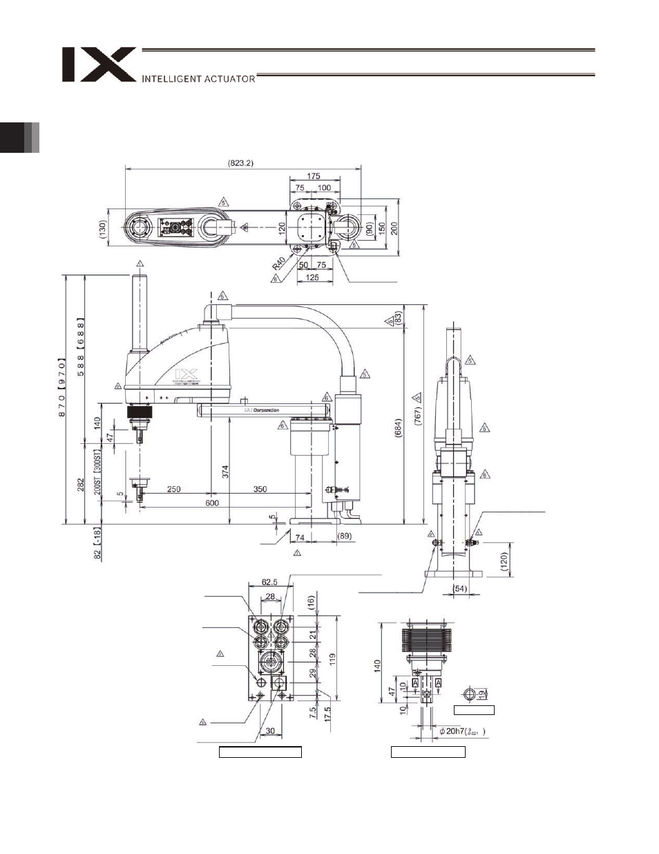
2. External Dimensions
IX-NNW60
H
4-
11
24, counterbore depth 5
Note 1: External force applied to the spacers
must not exceed 30 N in the axial
direction or 2 N
m in the rotating
direction (for each spacer).
Note 2: The LED operates only when the user
provides a circuit that receives
controller I/O output signal and
supplies 24 VDC to the LED terminal
in the user connector.
Note 3: Insert a tube of
12 in outer diameter
into the intake/exhaust port and
extend the tube to a place not
exposed to water.
(M
echanical end
)
Reference
surface
44
14 hollow
Quick joint for
6 air tube
User connector (user
wiring connector, 23 pins)
BK SW
(Brake-release switch)
Spacer outer
diameter
7
Height 10,
M4, depth 5
(Note 1)
Detail View of Panel
Quick joint for
4 air tube
ALM (Note 2)
Detail View of End
Section A-A
Air supply port for air
purge: Outer diameter
6 (inner diameter 4)
Intake/exhaust port (Note 3)
Red
Yellow
Black
White