IAI America IX-NSN6016H User Manual
Page 109
101
1
1. Precautions for Use
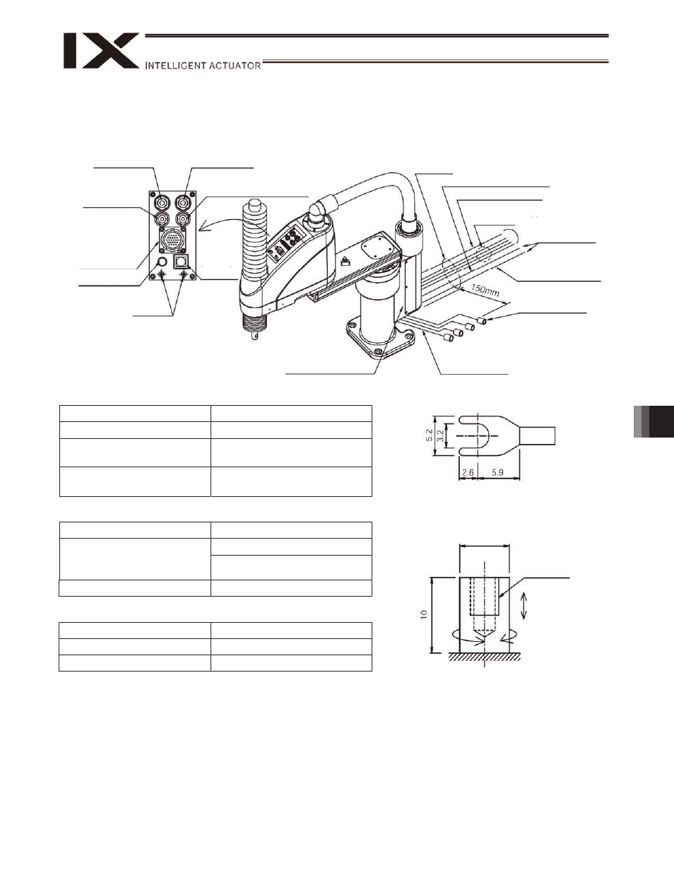
Shape of Y-terminal
Spacer for user part installation
M4, depth 5
30 N or less
2 N
m or less
External force applied to the spacers must
not exceed 30 N in the axial direction or 2
N
m in the rotating direction (for each
7
11.5.2 IX-NNW50
H/60 H/70 H/80 H
User connector specifications
Rated voltage
30 V
Permissible current
1.1 A
Conductor size and number
of wires
AWG 26 (0.15 mm
2
), 24wires
Other
Twisted-pair cable (1 to 22),
shielded (Pin 24)
Piping specifications
Normal service pressure
0.8 MPa
4 mm x 2.5 mm, 2 pieces
Dimensions (outer diameter x
inner diameter) and number
of tubes
6 mm x 4 mm, 2 pieces
Working medium
Air
ALM (indicator) specifications
Rated voltage
24 VDC
Rated current
12 mA
Illumination color
Red LED
Quick joint for
6
(red) air tube
ALM (indicator)
Spacer for user
part installation
BK SW
Brake-
release
switch
U cable (outside robot)
Standard
5 m
Air tube
4 (black, white)
6 (red, yellow)
Quick joint for
4
(black) air tube
User connector
Waterproof
connector, 24 pins
(24 pins include a
shield terminal.)
4, 6 quick joints
(2 pcs each)
BK power-supply cable
(outside robot)
M cable (outside robot)
PG cable
(outside robot)
Terminal: Y terminal
Air supply port for air purge on
opposite side
Applicable tube: Outer diameter
6
To controller
Quick joint for
6
(yellow) air tube
Quick joint for
4
(white) air tube