36 4. w iring diagram – IAI America IX-NSN6016H User Manual
Page 44
36
4. W
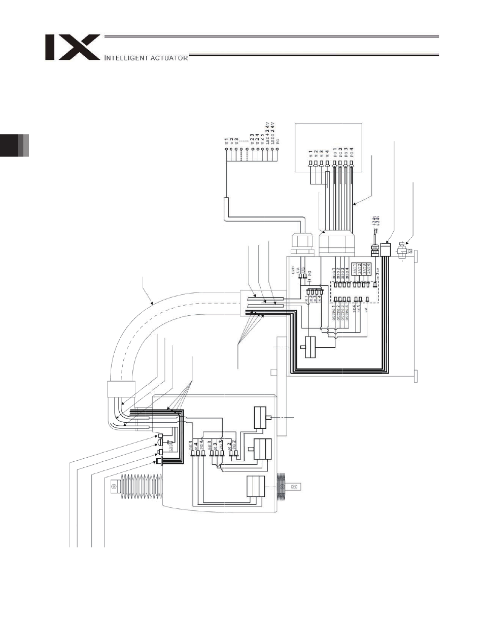
iring Diagram
W
a
te
rp
ro
o
f con
nect
or
for
uaser
w
ir
ing
(
24 pin
s
)
24 pi
ns inclu
d
e a
shiel
d ter
minal
Al
ar
m L
E
D
Br
ake-
re
leas
e sw
itch for
ax
es
3
/4
(Z/R-a
x
e
s)
Air joint
Black (
4
), Ye
llo
w
(
6)
,
R
ed
4)
, W
h
ite
(
4)
PG ca
ble (
inside
r
o
bo
t)
M ca
b
le
(in
side
ro
bo
t)
U cable (
insid
e
r
o
b
o
t)
F
lex
ibl
e
cable
U cable (
insid
e
r
o
b
o
t)
M
cable (
insid
e
r
o
b
o
t)
PG ca
ble (
inside
r
obo
t)
Ai
r tubes
U cable (
o
utside
r
o
b
o
t)
User
w
ir
ing
ter
minals
Co
n
tro
lle
r
M
cable (
o
utside
r
o
bo
t)
PG ca
ble (
o
u
tside r
o
bo
t)
4-ax
is
en
coder
4-a
x
is
m
o
to
r
4-a
x
is
brak
e
3-a
x
is
brak
e
3-a
x
is
m
o
to
r
3-ax
is
en
coder
2-ax
is
en
coder
2-a
x
is
m
o
tor
Ai
r tubes
1-ax
is
en
coder
1-a
x
is
m
o
tor
Air joint
Black (
4
), Ye
llo
w
(
6)
, R
ed (
4)
, W
h
it
e
(
4)
Br
ake p
o
w
e
r
term
in
als
Boar
d
Ai
r s
uppl
y
por
t
for
ai
r p
ur
g
e
This manual is related to the following products: