External dimensions, 17 2. external dimensions, Ix-nnn50 h – IAI America IX-NSN6016H User Manual
Page 25
17
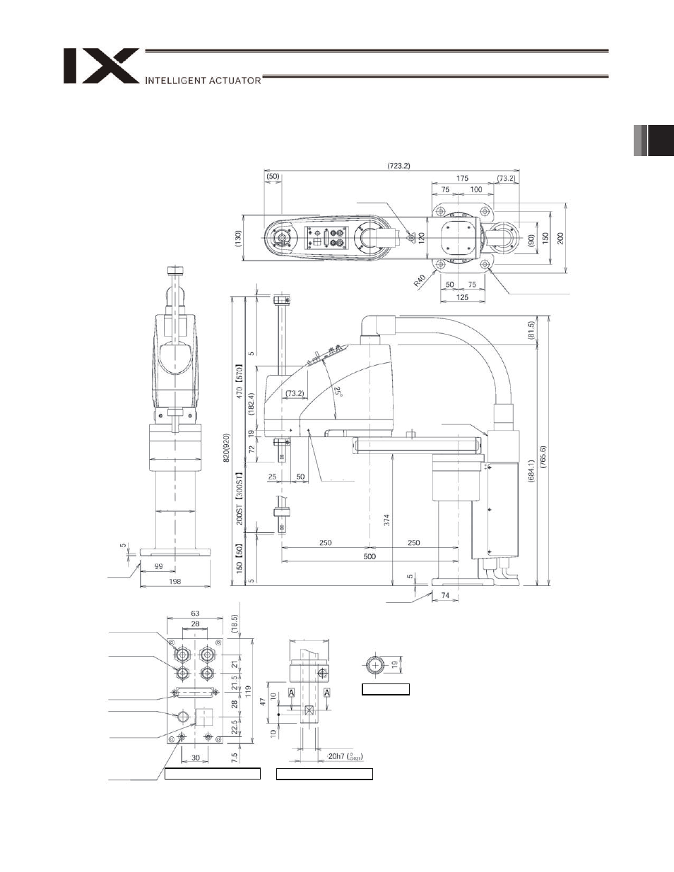
2. External Dimensions
2. External
Dimensions
IX-NNN50
H
Arm 2
stopper
4-
11
24, counterbore depth 5
Reference
surface
2-M4, depth 8
Same on
opposite side
(Note 1)
Note 1: The holes denoted by "2-M4, depth 8" are through
holes connecting both sides of the arm. Take note
that long mounting screws may contact the internal
mechanism parts.
Note 2: External force applied to the spacers must not exceed
30 N in the axial direction or 2 N
m in the rotating
direction (for each spacer).
Note 3: The LED operates only when the user provides a
circuit that receives controller I/O output signal and
supplies 24 VDC to the LED terminal in the user
connector.
(M
echani
cal
end)
(M
ec
han
ic
al end)
Reference
surface
Arm 1,
arm2
stopper
44
14 hollow
Quick joint for
6 air tube
User connector
(D-sub connector
for user wiring)
(25-pin, socket,
fastener size M2.6)
BK SW
(Brake-release
switch)
Spacer outer
diameter
7
Height 10, M4,
depth 5 (Note 2)
Detail view of panel (1/2)
146
112
Quick joint for
4 air tube
ALM (Note 3)
Detail view of arm end
Section A-A
Red
Yellow
Black
White