37 4. w iring diagram – IAI America IX-NSN6016H User Manual
Page 45
37
4. W
iring Diagram
Flex
ible
cable
Brake p
o
w
e
r
term
in
als
User
w
ir
ing
term
in
als
Cable
fi
x
cap
(C
apc
on)
M
c
abl
e
(ou
ts
ide
robot)
S
e
rvo
m
o
tor
fo
r
ax
is
1
(ar
m
1)
PG
c
abl
e
(i
ns
ide
robot)
M
c
abl
e
(i
ns
ide
robot)
U
c
a
b
le
(ins
id
e
ro
bot)
S
e
rvo
m
o
tor
for
axi
s
2
(ar
m
2)
Serv
o
m
otor
with
brak
e
fo
r
a
xi
s
3
(Z-axi
s)
Serv
o
m
otor
with
brak
e
fo
r
a
xi
s
4
(R-axi
s)
FG
(t
o
D
-s
ub
ho
us
in
g)
D-sub
c
onnect
or
fo
r
u
ser
w
iri
n
g
(15
-p
in
, so
ck
e
t)
Alar
m
LED
Brak
e-releas
e
s
w
itc
h
for
ax
es
3/4
(Z/R-ax
es
)
Air
jo
in
t,
blac
k
(
4)
A
ir
joint,
re
d (
6
)
Air
jo
int,
whit
e (
4)
Air
jo
int, r
e
d
(
6
)
Air
joi
nt,
y
e
llo
w
(
6)
A
ir
jo
in
t,
b
la
c
k
(
4
)
FG
(T
o
base)
PG
c
abl
e
(ou
ts
ide
robot)
BK
po
wer
c
abl
e
(outs
ide
ro
bot)
U
c
a
b
le
(outs
ide
ro
bot)
Dedic
a
ted
batt
er
ies
for
IX
:
AB-3
Boar
d
Air
joint,
whit
e (
4
)
Air
joint,
y
e
llo
w
(
6)
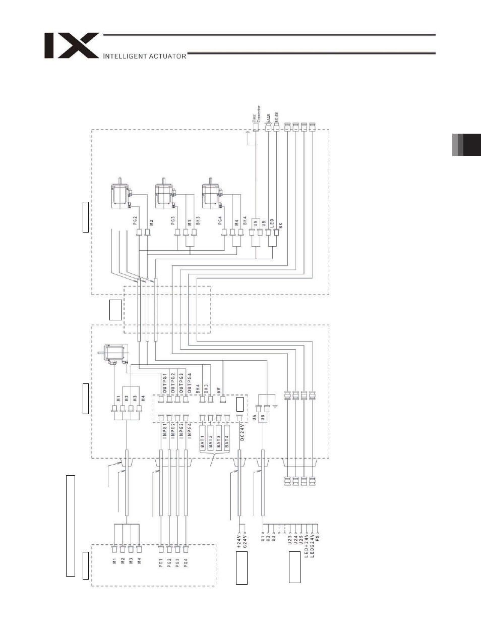
Wiring/Piping Diagram: 500/6
00
Controlle
r
Inside
bas
e
Inside
ar
m
2
Not
es
(1)
The
actual
lay
out
o
f
board
conne
ctor
s
v
aries
from
thi
s
dra
w
ing.
(2)
Since
th
e
br
ake
po
w
er
circui
t
is
prov
ided
on
the
primary
side
(high
-v
oltage
si
de),
a
d
edica
ted
24
V
p
ow
er
supply
is
require
d
for
this
circuit.
The
24
V
pow
er
su
pply
for
I/O
cir
cuits
used
on
the
seco
nd
ary
side
(low
-v
oltage
si
de)
cann
ot
be
shared.
(3)
To
opera
te
the
alar
m
LED,
the
u
s
er
m
ust
prov
ide
a
ci
rcui
t
tha
t
use
s
th
e
con
tr
oller
I/O
ou
tpu
t
sign
al.
IX-NSN5016H/ 6016H
φ
φ
φ
φ
φ
φ
φ
φ