34 4. w iring diagram – IAI America IX-NSN6016H User Manual
Page 42
34
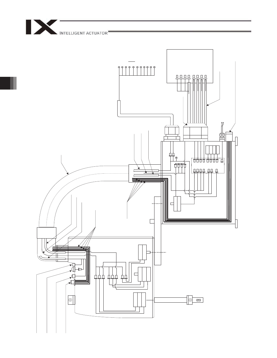
4. W
iring Diagram
M
D-sub con
nect
o
r
for us
er
w
iring
(25-oin,
sock
et)
Al
ar
m
L
ED
Brake-releas
e sw
itch for ax
es 3/4
(Z/R-ax
e
s)
Air
joint
Re
(
4
),
Yellow
(
6),
B
la
ck
(
4),
W
h
it
e
(
4)
PG ca
ble (inside
robo
t)
M cable (insid
e
rob
ot)
U cable (insid
e
rob
ot)
Flex
ible
cable
U cable (insid
e
rob
ot)
M
c
able (insid
e rob
ot)
PG ca
ble (inside
robo
t)
Air
tubes
U cable (o
utside
rob
o
t)
User
w
iring
terminals
Controller
M cable (o
utside
robo
t)
PG ca
ble (ou
tside ro
bo
t)
Brake p
o
w
e
r
terminals
Boar
d
LED
BK4
M4
PG4
BK3
M3
PG3
M2
PG2
LED
UA
U
B
FG
M1
M2
M3
M4
OUT
P
G1
OUT
P
G2
OUT
P
G3
OUT
P
G4
INPG
1
INPG
2
INPG
3
INPG
4
BK
4
BK
3
SW
BAT
1
BAT
2
BAT
3
BAT
4
24
V
DC
+24
V
G
24V
M1
M2
M3
M4
PG1
PG2
PG3
PG4
FG
LED
G2
4
V
LED
+
24V
U25
U24
U23
U3
U2
U1
4-
ax
is
en
c
oder
4-
ax
is
m
otor
4-
ax
is
br
ak
e
3-
ax
is
br
ak
e
3-
ax
is
m
otor
3-
ax
is
en
c
oder
2-
ax
is
en
c
oder
2-
ax
is
m
otor
Air
tubes
1-
ax
is
en
c
oder
1-
ax
is
m
otor
Air
joint
Re
(
4
),
Yellow
(
6),
Black
(
4
),
W
h
it
e
(
4)
φ
φ
φ
φ
φ
φ
φ
φ