Aster, Lave, Iring – Controlled Products Systems Group SWINGSMART DC 20 User Manual
Page 96: Onnections, Figure 5-2
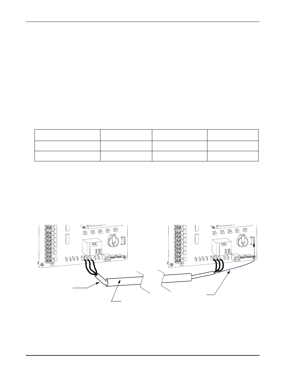
Master and Slave Wiring Connections
5-2
SwingSmart DC Installation and Reference Manual
Revision E
COM
EXIT
LOOP
BLOCK
EXIT
IN OBS
LOOP
OUT OBS
LOOP
CENTER
LOOP
EDGE
EYE
COM
+ 24 V
EMERG
OPEN
SHOW
LEDs
RADIO OPTIONS
EDGE +24V OP
EN COM
DUAL GATE
B
A
U
SE
R2
COM NO
DC
USER 1
COM
EXIT
LOOP
BLOCK
EXIT
IN OBS
LOOP
OUT OBS
LOOP
CENTER
LOOP
EDGE
EYE
COM
+ 24 V
EMERG
OPEN
SHOW
LEDs
RADIO OPTIONS
EDGE +24V OP
EN COM
DUAL GATE
B
A
U
SE
R2
COM NO
DC
USER 1
•
Complete the installation of both operators as separate machines and verify that their basic functions are
correct as solo operators before interconnecting them.
•
External control inputs, vehicle detectors and entrapment protection sensors may be connected to either
gate operator without regard to preference.
•
Be sure both operators are running the same software version. The software version is available on the
display by pressing the RESET button on the operator. The software version appears beneath the word
HYSECURITY. Keep the most current software loaded. It is available at www.hysecurity.com. Make it
part of your maintenance routine to check for software upgrades on a regular basis.
•
Both operators can be connected to the same 20A circuit breaker in the main panel. The wire size affects
operator performance. Use the following chart as a guideline to size wire for the given distance from the
power source to BOTH operators.
Table 5-1. Wire Length Chart
M
ASTER
AND
S
LAVE
W
IRING
C
ONNECTIONS
Figure 5-2.
AC Power - Dual Operators
14 gauge wire
12 gauge wire
10 gauge wire
115V
305 ft (95 meters)
500 ft (150 meters)
775 ft (240 meters)
230V
1220 ft (370 meters)
1950 ft (590 meters)
3100 ft (940 meters)
Master
Slave
Conduit (in the ground)
Shielded cable
(3-wire)
Shield wire
Ground
Note: Do NOT connect the ground shield wire
at both ends.